Showing posts with label Honda Manuals. Show all posts

Honda Civic & Acura 1.6 EL 1990-1993 Acura Integra TWM

Download Here
This install manual is available for download … twmperformance.com 1988-2000 Honda Civic & Acura 1.6 EL 1990-1993 Acura Integra TWM … This warranty is limited to repair or replacement … Unscrew the stock shift knob by rotating it counter clockwise. 2. Remove all screws securing center console and remove console. – 2 – This install manual is available for download in color at: www.twmperformance.com 3. Remove the rubber dust boot surrounding the shifter, use caution not to damage it. Put it in a safe place for re- …
https://blogger.googleusercontent.com/img/b/R29vZ2xl/AVvXsEjU-mhorreRMxmtXb62DtSq059qvWn7UH5OIVDVRl4wL91u1Ata-ob1Hd7DxLKv-jtAXjrbyGyEItMsJKdUgUOUXou2n7DrpQOfelbaolni7Shjs1_mqfVYoae9N-Q_IidN2fcavIkeynHI/s1600/Civic_imagebanner_civic-tengah.jpg
- 3 – This install manual is available for download in color at: www.twmperformance.com 6. Remove both bolts securing the shift assembly to the under side of the chassis with a 12mm socket and ratchet. 7. Remove the bolt at the transmission end of the shift rod with a 12mm or 14mm (depending on model) socket and ratchet. It may be necessary to use a 12mm or 14mm wrench if space is limited. 8. Remove the shift assembly and shift rod from the car. It may be necessary to disconnect the rubber exhaust hangers to have enough space to remove the shifter and shift rod.
- 4 – This install man

HONDA COMMON SERVICE MANUAL PDF

https://blogger.googleusercontent.com/img/b/R29vZ2xl/AVvXsEi_W31uJGF5uK46UlwUAegQFCuXXn1CwLOTwxHxwFLxkGw1srl32mkQpYx7Zu3WyPNX0VioecLyK6ljrU_TqfNVypGlI-HhpuxAsc0_2hrOaqvdse-5XixoXGioAkybC-lPsn1xfrbQlNA/s400/Honda_Logo_01.jpg


Short Description
Detailed description of standard workshop procedures, safety principles and service operations are not included. It is important to note that this manual contains some warnings and cautions against some specific service methods which could cause PERSONAL INJURY to service personnel or could damage a vehicle or rencer it unsafe. Please understand that those warnings could not cover all conceivable ways in which service, whether or not recommended by Honda.

Website: www.nighthawk750.com | Filesize: 7655kb
No of Page(s): 393

Content
This manual explains the theory of operation of the various systems common to HONDA motorcycles and motor scooters and ATVs. It also provides basic information on troubleshooting, inspection and repair of components and systems found on these machines.
Refer to the Model Specific Service Manual for the model you are servicing for adjustments, maintenance and repair information for components on that model.

Special tools are designed to remove or replace a specific pat or assemblies without damage. The use of other procedures, without using the specified special tools, may damage the parts.
Clean the outside of a part or assembly before removing it from the motorcycle or opening its cover for service. Dirt which has accumulated on the outside could fall into the engine, chassis or brake system and cause damage later.


Get the file Download here

HONDA TECH MANUAL PDF

https://blogger.googleusercontent.com/img/b/R29vZ2xl/AVvXsEhtmQ6ELVduIKtl4FjFtZg95NhuGyGojoj5OSW74tsyuzRdYZxiJQ17DREWFbB3xR8JqHvj0hKKINOW9nfMeIc5qPOX8eF21SWwlwDTZ1_YRHBkuUh4fxB8Gtr5Lo3h6TjCp1wCv0cI0xo/s400/Acura-TL-4.jpg


Short Description
1. Only stock Honda GX160K1 HX2 and HX26* engine and gearbox will be used in this class. All parts will be stock Honda specifically made for the Honda GX160OK1 HX2. U.S. # GCACK & GCAAK – Canada #GCABT
A. All 160 Honda engines must be updated to the new E2 Style piston and cylinder head.
B. Failure to update = DQ and Minimum 6 month suspension

Website: www.i-5qmc.com | Filesize: 986kb
No of Page(s): 19

Content

Factory air cleaner must be removed. Any air filter may be attached to the outside of air filter adapter. Outer wear style or equivalent can be used over carburetor only with no adapter. The approved air filter adapter may be run with or without an air filter. Any air filter may be used with adapter as long as there are no devices inside the air filter or adapter. (I.E. Springs not allowed) Hose from valve cover must go into a catch can. (We are using “outerwear” to define a style not brand name).
1. The use of air filters during qualifying at asphalt and dirt events is illegal. The Senior Tech. Official reserves the right to allow filters at any event that it’s deemed necessary. Senior Tech. Official reserves the right to allow filters at any event that it’s deemed necessary.


Get the file Download here

Honda GL1800 Specific Instruction Manuals

https://blogger.googleusercontent.com/img/b/R29vZ2xl/AVvXsEjC7oM3MzPEWk1qF9Z_kNLUVBdT1IX1Lx-mnlaPpS0o09A9eeG8LPA1hgcF8b9Ima9UzbUH_1J_DsojbcSx_h-8Tn5UVSgjpTsTGxuX2gdf1HNwCz6NS74FMZmK3jLCW1K7afffeUA3j9E/s400/HONDA+GOLDWING+1800cc+2009+glow.png


Short Description
This complete plug and play kit comes with two different power cables (only one will be used). You will decide if your lighted switches will be powered only when the bike ignition key is in the “on” or the “accessory” position or if they will be “always hot”. The “always hot” option is ideal for parking lights, parade style lights or anything you may want turned on when the key is either on or off. This is the recommended choice for use with an Owl Knight Rider, Windshield Lights or Owl’s Eyes on the GL1800. Use the appropriate installation instructions below.

Website: www.owllighting.com | Filesize: 1017kb
No of Page(s): 6

Content
Installation Instructions for “Always Hot” Switches
• Remove the following items per the Honda Service manual.
Seat
Left side battery cover
Left or Right side under handlebar cover
Left or Right side Pocket
• Carefully run the red/black power cable from the battery into the pocket on the same side your switches will be mounted. Start from the battery with the plastic connectors and route the wire along the upper frame member and under the edge of the top shelter, leaving the end with the battery ring terminals and fuse near the battery. Fish the wire into the faring pocket opening. Allowing enough wire to reach the battery terminals, pull all of the extra wire into the pocket area.
• Remove the ground wire from the battery and attach the ground (Non-fused) wire from the power cable, replace the battery ground bolt and secure it.
• Remove the positive wire from the battery and attach the positive wire (with the fuse holder) to the positive terminal of the battery, replace the battery bolt and secure it, replace the rubber boot over the positive battery terminal.


Get the file Download here

Honda GX22 GX31 Repair MANUAL

https://blogger.googleusercontent.com/img/b/R29vZ2xl/AVvXsEg4YqMwOlfLVTuDd1jwNhg9ZHQbZOw3vUH807pE9V5OSfMcf4COtL2rDYukdH8Uj2YWOkIPcB6Ef8sIPVUSikSoKzKdGYpDtxRlKfmXmLAojvIuJPC29IVh2cEdzE_jf-xSYlkgdvg6Hg8O/s400/2008+Honda+Accord+engine.jpg


Short Description
Thank you for purchasing a Honda engine. This manual covers the operation and maintenance of your engine: GX22 - GX31 All information in this publication is based on the latest product information available at the time of printing. Honda Motor Co. Ltd. reserves the right to make changes at any time without notice and without incurring any obligation. No part of this publication may be reproduced without written permission. This manual should be considered a permanent part of the engine and should remain with it if it is resold.

Website: www.waterrauk.com | Filesize: 667kb
No of Page(s): 16

Content

1. Engine oil level
CAUTION:
- Running the engine with insufficient oil can cause serious engine damage.
- Be sure to check the engine on a level surface with the engine stopped.
1. Place the engine horizontally on a level surface.
2. Remove the oil filler cap and check the oil level: it should reach the top of the oil filler neck.
3. If the level is low, fill to the top of the oil filler neck with the recommended oil.
Every 10 hours, check the engine oil level and replenish oil up to the top of the oil filler neck if the engine is operated for more than 10 hours continuously.

Use Honda 4-stroke, or an equivalent high detergent, premium quality motor oil certified to meet or exceed U.S. automobile manufacturer’s requirements for service classification SG, SF. Motor oils classified SG, SF will show this designation on the container. SAE 1OW-30 is recommended for general, all temperature use.


Get the file Download here

Honda Manual Transmission

https://blogger.googleusercontent.com/img/b/R29vZ2xl/AVvXsEjP7t6fGRRlNwfsIM-w1lNsbEf0xORV9Ha53_wJbulVA8kLVluBBiuXp8C6UKn5CHqCrPrJJAubjl5KUeyqUgELeCeLgzcicLgGlUvr0fygGcyMKrXRSWtItsKbBWExKNhUQNwD_5no1kVD/s400/2007+Honda+Civic+Type+S+1.8+i-VTEC+3d+interior.jpg


Short Description
The shift lever feels hard to move from gear to gear, or the manual transmission pops out of 2nd or 5th gear, usually during deceleration. The shift cable end is corroded at the transmission, which causes a stiff feeling when shifting (this may also cause the transmission to pop out of gear). The clearance between the interlock and transmission case wall is too large, and 2nd or 5th gear tooth contact length is too short, causing the transmission to pop out of gear.

Website: honda.justanswer.com | Filesize: 208kb
No of Page(s): 4

Content

Replace the cable bushings if corroded, or replace the transmission case housing, 1-2 shift fork, 2nd gear set, 1st gear, and 5th gear.

DIAGNOSIS
Test-drive the vehicle. Shift through all five gears and then back down to 2nd, and check if it is difficult to shift into gear. Accelerate at wide open throttle in 2nd or 5th gear, and quickly release the gas pedal; do this several times.
• If the transmission only has a stiff feel when shifting, go to REPAIR PROCEDURE A.
• If the transmission only pops out of gear, go to REPAIR PROCEDURE B.
• If the transmission has a stiff feel when shifting and pops out of gear, do REPAIR PROCEDURE A first, and then do REPAIR PROCEDURE B if needed.


Get the file Download here

Honda TRX400EX Installation Instruction

https://blogger.googleusercontent.com/img/b/R29vZ2xl/AVvXsEhuGbPcFnyPQmX8EetLBTFJGoOmInAVVIxlBAlKsgcbhr7YSL-XLxPub9fpWUol3sa1-12jyq2-zIh48lZSO35avMfPqWH9_FyvzD5Et58lejT5Ys-K4UfA6ahtvs3zxcmKqDFE2VW5mrE/s400/Mugen_Honda_Odyssey_002.jpg


Short Description
Spark Output: The Enhancer Ignition System for the Honda 400EX produces a high output spark that is approximately double the stock spark output. This increased spark energy allows the use of richer fuel mixtures or even exotic fuel such as alcohol. The MSD Ignition will put out approximately 30,000 volts to the spark plug.

Website: www.msdpowersports.com | Filesize: 629kb
No of Page(s): 8

Content
Spark Plugs: With the MSD Enhancer, it is recommended to use as cold a spark plug as possible while still being able to start the engine easily. The spark plug gap will largely depend on the compression of the engine. The higher the compression the smaller the plug gap you must run. A good rule of thumb for the spark plug gap is between .032” and .036”. Taking the time to test with different gaps will give you the best gap for your application.
MSD Coil and Spark Plug Wires: The MSD Coil features low resistance (0.2 Ohms Primary, 2K Ohms Secondary) with a turns ratio of 70:1 for maximum spark voltage and energy. The 8.5mm Super Conductor Spark Plug Wires are very low resistance (less than 50 Ohms per foot) for maximum voltage carrying capabilites. Even with this low resistance, the wire still suppresses EMI (Electro Magnetic Interference) from disrupting the electronics of the ignition. This is the only wire recommended to be used with the MSD Enhancer Ignition System.


Get the file Download here


Civic Rear Main Oil Seal Leaks

http://3.bp.blogspot.com/_FoXyvaPSnVk/TGQz71XRkiI/AAAAAAADMSw/61JI12R7C0Q/s1600/Honda-Civic-Lexus-Crown-3.jpg

Civic Rear Main Oil Seal Leaks
Short Description
SYMPTOM
The engine leaks oil between the block and the transmission.
PROBABLE CAUSE
The rear main oil seal (crankshaft oil seal) is contaminated.

Website: www.honda-fanatics.nl | Filesize: 71kb
No of Page(s): 2

Content
DIAGNOSIS
Clean the area with a shop towel where the engine block and transmission meet. Start the engine, and look for oil leakage from the area with the aid of a powdered leak detector.
• If you see any signs of leakage, go to REPAIR PROCEDURE.
• If you see no signs of leakage, then what looked like leakage may have been excess residue from a previous repair on another part. Continue with normal troubleshooting.
REPAIR PROCEDURE
1. Remove the transmission. Refer to section 13 or 14 of the appropriate service manual.
2. Remove and discard the rear main oil seal (crankshaft oil seal).
3. Install the new oil seal. Refer to page 7-29 of the ‘96–00 service manual or page 7-27 of the ‘01 service manual.
4. Reinstall the transmission.
5. Reinstall the drain plug with a new sealing washer.
6. Refill the transmission with the appropriate fluid.


Get the file Download here

Honda GXV50

https://blogger.googleusercontent.com/img/b/R29vZ2xl/AVvXsEiZSuLFHzsDx_G2xCrk9k37ZaR9TBW3L4SBKnlcAsxXykz3z4S_pGAjiNQVYjUT9YDVcidxl7YU9pCl1TvHAa9A8rsynQ4bJBiXqJ2pAJyrRfJP19IKOrMjVwrxFXzCv2PRJ3EdgAD98yE/s400/htup_0808_06_z%252B1996_honda_civic_coupe_ej%252Bb16b_engine.jpg

Short Description
Proper service and repair procedures are vital to safe, reliable operation of Go-Karts and Bumper Boats as well as personal safety of those performing repairs. Refer to your J&J Service Manual for servicing and repairing J&J Go-Karts and Bumper Boats. Always use safe and effective methods. The Service Manual contains many NOTES, CAUTIONS and WARNINGS which should be followed along with standard safety procedures to eliminate the possibility of personal injury or improper service which could be damaging to your equipment or compromise its safety.

Website: www.funpartsxpress.com | Filesize: 3150kb
No of Page(s): 25

Content
It is important to note that repair procedures, techniques, tools and parts for servicing Go-Karts and Bumper Boats as well as the skill and experience of the individual performing work vary widely. It is not possible to anticipate all conceivable ways or conditions under which Go-Karts and Bumper Boats may be serviced or to provide cautions to all possible hazards that may result. Standard precautions should be used when handling toxic or flammable fluids, and safety goggles or other protection should be used during cutting, grinding, chiseling, prying or any other process that can cause material removal or projectiles. J&J recommends use of safety goggles or approved glasses during all servicing.
All information contained in this Parts Guide is based on the latest product information and prices available at time of printing. We reserve the right to make changes at any time without notice. No part of this publication may be reproduced, stored in a retrieval system or transmitted, in any form by any means, electronic, mechanical, photocopying, recording, or otherwise, without the prior written permission of J&J Amusements, Inc. A Corporation of Oregon. This includes text, figures and tables.


Get the file Download here

Honda GL1800 Trailer Hitch Installation Instructions

https://blogger.googleusercontent.com/img/b/R29vZ2xl/AVvXsEi2F5L-o9hY-ucjIhbkaH2sontYgfKWj_lQ4mVUGGjEA1HCFzvp3zeS8EJ9XnVXaX3ZZ_FZGhscsM8BlkF88NB96sXju4pVWQWpDTSKTVocHuqisFz54k_SOZTzbpYgZAMkegjXqPvkmNU/s400/HONDA+GOLDWING+1800cc+2009.png

Honda GL1800

Short Description
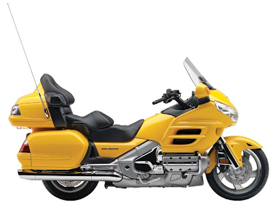
THE BUSHTEC GL1800 VERTICAL RECEIVER HITCH SYSTEM HAS BEEN EXCLUSIVELY DESIGNED FOR USE ONLY ON A STOCK HONDA GL1800. IT WILL NOT WORK ON ANY OTHER MOTORCYCLE. ANY MODIFICATION TO ANY PART OF THIS HITCH, INCLUDING BUT NOT LIMITED TO ALTERING THE SUPPLIED HARDWARE OR IMPROPER INSTALLATION COULD CAUSE INJURY OR DEATH AND IMMEDIATELY VOIDS ANY AND ALL WARRANTIES.

Website: www.bushtec.com
Filesize: 70kb
No of Page(s): 9

Content

1. Place the motorcycle on its centerstand on level ground. Remove the four bolts in the seat handles with a 6mm Allen head socket and remove the seat. NOTE: The rubber bushings inside the seat may fall out during removal; Make sure they are in place upon reassembly.
2. Remove both side covers.
3. Remove the (5) five bolts in the rear fender (license plate panel, between saddlebags) with a 5mm Allen head socket. Remove the rear fender. NOTE: The fifth bolt is behind the license plate.
4. Remove the (3) three bolts in the passenger floorboard holder cover with a 5mm Allen head socket. Remove the cover and repeat for other side.
5. Remove the (2) bolts in the rear saddlebag guard with a 12mm socket. Remove the saddlebag guard and repeat for other side.
6. Remove the bolt in the muffler hanger using a 12mm socket. Repeat for other side.
7. Loosen, but do not remove, the muffler clamps using a 6mm Allen head socket. Rotate the mufflers down slightly to allow the hitch hoop to slide between the mufflers and the saddlebags.


Get the file Download here

Honda CR 125/250R Installation Instruction manuals

https://blogger.googleusercontent.com/img/b/R29vZ2xl/AVvXsEjV15ZfGcgOWxvpuddBkovvIqB-GCTMaL9mZ98LeQggQzWrCnAq42tP0F5ZefkktqiKG5VlYAVbgkDCG2uQshOD8J2OegDt2SUCpBUmHnPebi2H8eKKHIOvDrtnIY0Wfc0nevkeUaO-894A/s730/2010+Porter+Honda+CR250R---1-13-10-printable.jpg

Honda CR 250R

Short Description
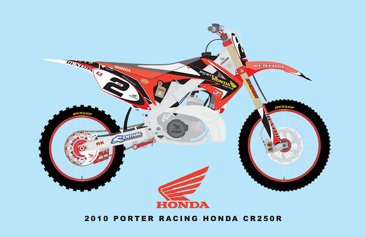
Note: The MSD Enhancer Ignition, PN KT4201, for the Honda CR 125 or CR 250R motorcycle is designed as a complete system. No part may be substituted with the stock ignition system.

Website: users.atw.hu
Filesize: 179kb
No of Page(s): 4

Content

The following explains some technical aspects of the Enhancer Ignition.
Battery: The battery is necessary to the operation of the Enhancer in two regards.
• The battery supplies voltage to the complex timing feature of the Enhancer.
• The Enhancer has a built in boost circuit that amplifies the spark energy at low rpm where the stock magneto is insufficient.
The MSD NiCad Battery pack, PN 4381, must be charged with the recommended battery charger or an MSD Fast Charger, PN 4385. The battery should be completely discharged before recharging. If a 7.2 Battery Charger is used, the recommended time for charging is seven hours. With the MSD Fast Charger the battery only needs to charge for one hour.


Get the file Download here

Honda Service Bulletin Safety Recall Ignition Switch

https://blogger.googleusercontent.com/img/b/R29vZ2xl/AVvXsEgkosn8L5ZLsbMDjB9hEo11ckMYiN0MR0Sfcq1-WMiH1xHVaAzI41uS-UGzT1b4_xsxfIgnMCsmGrNQb3iIRNiIi62BmmRSNkOUPrvorDXHiewehtTy1ZRFN2Zg8fKTAQUILr0YMEnrhx_I/s1600/2011-Honda-Odyssey-18.JPG

Honda Service Bulletin Safety Recall Ignition Switch

Short Description
Electrical contacts in the ignition switch can wear prematurely due to high electrical current passing through the switch. Worn out ignition contacts could cause the engine to stall without warning. Although the engine will restart in most cases, a vehicle that stalls while driving increases the risk of a crash.

Website: www.alancoxautomotive.com

Filesize: 586kb
No of Page(s): 7

Content

Not every vehicle in the years and models listed above is affected by this campaign. Before beginning work, verify that the vehicle is eligible by checking at least one of the following.
• The customer has a notification letter.
• The vehicle is shown on your campaign responsibility report.
• The vehicle is shown as eligible on a DCS or iN (Interactive Network) VIN Status Inquiry.

Procedure A: 1997 Accords (L4)
1. Remove the dashboard lower cover, the knee bolster, and the steering column covers (see the 1997 Accord Service Manual, page 23-75, steps 2 and 3).
2. Disconnect the 7P and 8P connectors from the ignition switch body.


Get the file Download here

Honda ENGINE BLOCK HEATER INSTALLATION INSTRUCTIONS

http://1.bp.blogspot.com/_FoXyvaPSnVk/THlLtomb96I/AAAAAAADPi4/pQq2JUPl1yA/s1600/Honda-CR-Z-Super-GT-04.jpg


Short Description
- Always use Honda Antifreeze/Coolant. Using a non-Honda coolant can result in corrosion, causing the cooling system to malfunction or fail.
- To avoid burning out the element, do not operate the engine block heater before it is installed in the vehicle or before you add coolant.

Website: www.cheaphondaparts.com | Filesize: 602kb
No of Page(s): 4

Content

1. Allow the engine and all cooling system components to cool down.
2. Make sure you have the anti-theft code for the radio, then write down the frequencies for the preset buttons.
3. Disconnect the negative cable from the battery.
4. Place a clean drain pan under the radiator drain plug, then remove the drain plug from the rear of the radiator to drain the coolant. Remove the radiator cap, and loosen the bleed bolt to increase the flow.
5. Remove the bolt with the washer from the engine block on the left side near the oil filter. Coolant remaining in the engine jackets will flow out of the bolt hole when the bolt is removed.


Get the file Download here

Honda Service Manuals-2002 Civic 3-Door and CR-V MIL

http://img216.imageshack.us/img216/1970/hondacivictyper20071it.jpg


Short Description
SYMPTOM
The MIL is on, and DTC P0341 [variable valve timing control (VTC) phase gap] is set.
PROBABLE CAUSE
The VTC control solenoid valve is temporarily stuck or contaminated.

Website: www.crvownersclub.com | Filesize: 82kb
No of Page(s): 1

Content

REPAIR PROCEDURE
1. Use the PGM Tester to read and clear the DTC(s).
2. Start the engine, and let it idle.
3. Check the engine idle:
• If the engine does not idle smoothly, go to step 4.
• If the engine idles smoothly, go to step 5.
4. Replace the VTC control solenoid valve. Refer to page 11-127 of the 2002 Civic Si Service Manual or page 11-133 of the 2002 CR-V Service Manual.
5. Make sure you have the Interactive Network (iN) CD (July ‘02 or later) loaded into your iN master terminal. If not, load the CD using the instructions that come with it.
6. Update the ECM/PCM software with the Honda Interface Module (HIM). Refer to S/B 01-023, Using the Honda Interface Module to Update Control Units/Modules.


Get the file Download here

Honda Service Bulletin - Clarification of Honda Unibody Repair Policy

https://blogger.googleusercontent.com/img/b/R29vZ2xl/AVvXsEgv8ypVVOhmPwxaGMcfeOfZLIWrQ1FuK-mhiP97ClLzMVP0voUJ2OrTD4X5Wv0qDU2wlRtuBwetMyZnQ04TiSc2gARFTYci170-ui5VnMkNPYAi1rf8D0W8Y4zjXSLOryafQ0xWtNG1xhk/s320/honda-crz-2.jpg

Short Description
Honda automobiles and trucks are built to precise standards so that they can perform well under many situations. For example, they offer a firm responsive ride yet yield when necessary under the forces of a collision to help protect the vehicle occupants.

Website: www.therodshop.com | Filesize: 86kb
No of Page(s): 1

Content

HONDA REPAIR POLICY
Sectioning Frame Components
When body repairs are necessary, Honda recommends that any repairs be performed by an experienced professional, using the Honda body repair manual, and that component replacement be accomplished along factory seams. Failure to do so can result in a number of problems, including improperly fitting parts, noises, tire wear, and most importantly, changes in vehicle dynamics and occupant protection in a subsequent crash.
In particular, Honda strongly recommends against the process of joining cut pieces from separate vehicles—commonly referred to as clipping. This is not an authorized Honda repair method. Any problem with other components resulting from such improper vehicle repairs is not covered under Honda’s factory or extended warranties.

Get the file Download here

HONDA 360/400/600 SEDAN & VAN SHOP MANUAL (2nd Edition)

https://blogger.googleusercontent.com/img/b/R29vZ2xl/AVvXsEg7m0Oh5L3znPeKV98eH6GEfOPy5gGlvVuAUNdPDlD4gBRq440-kaKU6XL7Ry_QkZa_0Cp9gD3VFgELRO5L4km95hjSyYd2mBR_mBgwPEslckl8GVAAGjBxJTdAEdqqtjx1FhVILuICl8Y/s400/Honda+Accord+sedan.jpg

Short Description
This manual is prepared to provide the service personnel of Honda dealers with complete informatoin on the maintenance and repair of Honda Car Models N360, N400, N600 and Station Wagon Model LN360 and their variants.
The information and instructions are grouped according to the type of work to be performed, such as diagnosis and testing, frequently performed adjustments and repairs, overhaul, etc. Specifications, special tools and maintenance instructions are found at each major section.

Website: www.honda600coupe.com | Filesize: 2458kb
No of Page(s): 35

Content

Keys and Locks
Locks of the identical structure are used for the ignition switch, doors and trunk lid so that a single key can serve a multiple purpose of ignition, and opening and closing of both door locks and the trunk lid.
Fig. 1D-1 shows the ignition switch assembly and the key, Fig 1D-2 the door locks, Fig. 1D-3 the trunk lid lock and the key.

a. Key
A six digit number is engraved on each key. The first figure of a number on a key represents its groove shape and the rest is angular shapes.
A blank key with only a groove shape and without angular shape has been prepared which makes it possible to duplicate a key by cutting angular shapes into it.
It is necessary for a motorist using the key to have a duplicate ready before he losses the key or when he wants spare keys on hand. Otherwise it may become necessary to change all three lock assemblies.

Get the file Download here

OWNERS MANUAL FOR A HONDA CT110 SERIES MOTORCYCLE

https://blogger.googleusercontent.com/img/b/R29vZ2xl/AVvXsEjmO2KvzWCMgOmwzBxlwicVOWUqd6y3WUHaPd5FgTceeyDDNjbDJGsqpel_uVqRUl7yHRFpgdMBHSRZ_oOtJPF_NQDodPET2R1WIR84Qm3_rJpSe1ksEsoI2VOkjPg3ZSUJOvC_QrY3O9I/s400/DSC00267_MED.jpg

Short Description
THIS IS A OWNERS MANUAL FOR A HONDA CT110 SERIES MOTORCYCLE. PLEASE BE ADVISED THAT THIS IS THE CLOSEST THING TO THE HARDKNOCK BOBBER. WE ARE NOT RESPONSIBLE FOR ANY INACCURACIES IN THIS MANUAL NOR MISUSE OR NON MAINTENANCE DONE ON YOUR BIKE. PLEASE READ WITH CARE AND USE COMMON SENSE. THANKS AND ENJOY YOUR HARDKNOCK BOBBER.

Website: www.shopbccycles.com | Filesize: 114kb
No of Page(s): 10

Content

Engine Oil Level Check
Check the engine oil level each day before riding the motorcycle. The level must be maintained between the upper (2) and lower (3) marks on the dipstick (1).
1. Start the engine and let it idle for a few minutes.
2. Stop the engine and hold the motorcycle in an upright position on firm, level ground.
3. After a few minutes, remove the oil filler cap/dipstick, wipe it clean, and reinsert the dipstick without screwing it in. The oil level should be between the upper and lower marks on the dipstick.
4. If required, add the specified oil up to the upper level mark. Do not overfill.
5. Reinstall the oil filler cap/dipstick, check for oil leaks.

Flooded Engine
If the engine fails to start after several repeated attempts, it may have become flooded with excess fuel. To clear the engine, turn off the engine stop switch and lower the choke lever to Fully OFF (B). Open the throttle fully and crank the engine several times with the kick starter. Turn the engine stop switch to RUN and open the throttle slightly; start the engine using the kick starter.

Get the file Download here

PDF MANUAL 2003 HONDA CIVIC 2-DOOR SPORT SUSPENSION INSTALLATION INSTRUCTIONS

https://blogger.googleusercontent.com/img/b/R29vZ2xl/AVvXsEhJj4N9CBsezoe0KL9uA10aE5s0KE0RlYDokRrBjCSafcstWXjkU6JFIW7TM5RQtFk-sVVS0JhbI6nCsNu_FuNiyTOBKqJiV0dZX-U1pph6Azx9-ZjQxCbQHARSC1tOR4LYyEUx0jL_frM/s320/civic+1.3+2door+jgf368+back.JPG

Short Description
NOTE:
• Inflate the tires to the specified air pressure.
• These instructions show the left damper assembly being installed; the same procedure applies to installing the right damper assembly.
• These dampers are designed to be used exclusively with this model and should not be used with other models.
• The dampers for the left and right sides are different. Be sure to note the “L” and “R” markings on the dampers for the proper installation.

Website: techinfo.honda.com | Filesize: 520kb
No of Page(s): 8

Content
Removing the Front Damper
1. With the vehicle on a rack, remove all four wheels.
2. Remove the cotter pin from the tie-rod end ball joint, and remove the nut.
3. Using ball joint remover tool, disconnect the tierod end from the steering arm of the damper assembly.
4. Remove the wheel sensor harness bracket, and the brake hose bracket from the damper. Do not unplug the wheel speed sensor connector.

Get the file Download here

PDF MANUAL 2009 HONDA CIVIC 4-DOOR SPORTS SUSPENSION INSTALLATION INSTRUCTIONS

https://blogger.googleusercontent.com/img/b/R29vZ2xl/AVvXsEh2ppoXj1l0KNhiEjSGs9GB-aNnMq1-eScN2JJuwrl0_k-0j4auYLLDIeYtn_qe_qnVpipK_V4gRklHwlhnY68mclhmkdCoQHNB4_EirRouwVgibWGSPe85whKbQuP2IF9o7dh6gbjZ3Qc/s400/Honda_Civic_Si_Concept,_2005.jpg

Short Description
INSTALLATION
NOTE:
• Inflate the tires to the specified air pressure.
• The dampers for the left and right sides are different. The damper marked R goes on the right side; the damper marked L goes on the left side.
• These dampers are designed to be used exclusively with this model and should not be used with other models.
• These instructions show the left damper assembly being installed; the same procedure applies to installing the right damper assembly.

Website: techinfo.honda.com | Filesize: 294kb
No of Page(s): 9

Content
Removing the Front Damper
1. With the vehicle on a rack, remove all four wheels.
2. Remove the wheel sensor harness clip and the brake hose bracket from the damper. Do not disconnect the wheel sensor connector.
3. Remove the damper pinch bolts and self-locking nuts from the damper. Do not allow the knuckle to rotate too far outward. This may allow the inner CV joint bearing to unseat.
4. Turn the ignition switch ON (II), then turn on the wipers. Turn the ignition switch off when the wipers are near the A-pillars.

Get the file Download here

Free download Honda 2007 Civic Coupe Owner’s Manual.pdf

https://blogger.googleusercontent.com/img/b/R29vZ2xl/AVvXsEhOyRsmj8yJkR-EGc3KhOVVVXJCNKNvfSpz63XIKfPtkSl_j1DRsyWyxCYhUtDdfvV2ZJiUNP9cznpJZBBoMAk7WBHsYOf2UP9kE3aAm4-eewcYklCwbJOw5LSUeG9JDo-tq6v5s8rj6CI/s400/09+Civic+Si+Coupe+3.jpg

Contents

Your Car at a Glance (main controls)

Driver and Passenger Safety (seat belts, SRS, and adolescent protection)

Instruments and Controls (indicators, gauges, dashboard, and council column)

Features (heating and cooling, audio, council wheel, security, and cruise control)

Before Driving (fuel, car break-in, and burden loading)

Driving (engine and manual operation)

Maintenance (minder, aqueous checking, accessory services, and car storage)

Taking Care of the Unexpected (flat tire, asleep battery, overheating, and fuses)

Technical Advice (vehicle specifications, tires, fuels, and emissions controls)

Warranty and Customer Relations (warranty and acquaintance information)

Authorized Manuals (U.S. only) (how to order)

Index

Service Advice Summary (fluid capacities and annoy pressures)

download Honda 2007 Civic Coupe Owner’s Manual.pdf