Showing posts with label Motorcycle Manuals. Show all posts

Ducati 999R 1/5 SCALE DUCATI 999R NITRO POWERED R/C MOTORBIKE

https://blogger.googleusercontent.com/img/b/R29vZ2xl/AVvXsEhE-yZhEF5jLeol5Gs3QVNTwdZ42x9jkRY6dU1VcEIH-kdjko0VxTINIEho96K6ElJRTHP3i24bynT0Qca7irlsYWvultZC4fdyJtIq5sYMLPnH2-X1Lke1gGonz9Z9lEwW4CCJYDI4ons/s800/ducati+999.jpg


Short Description
Thunder Tiger Corporation guarantees this model kit to be free from defects in both material and workmanship. The total monetary value under warranty will in no case exceed the cost of the original kit purchased. This warranty does not cover any components damaged by use or modification. Part or parts missing from this kit must be reported within 60 days of purchase. No part or parts will be sent under warranty without proof of purchase. To receive part or parts under warranty, the service center must receive a proof of purchase and/or the defective part or parts. Should you find a defective or missing part, contact the authorized Thunder Tiger Service/Distributor nearest you. Under no circumstances can a dealer or distributor accept return of a kit if assembly has started.

Website: www.acehobby.com | Filesize: 536kb
No of Page(s): 16

Content

1. Choose a fuel from a reputable, brand name company that is approved for car/truck use. Do not use airplane or boat fuels in your car/truck. Choose methanol based model engine glow fuel that has a nitro content in the range 10%-30% and 5% to 18% caster/synthetic oil content for lubrication. Lower nitro percentages will generally result in a cooler engine running temperature and therefore last longer before needing a rebuild; cooler-running engines also generally produce less power. 20% nitro is the most widely used fuel.
2. Fuel color is for identification purpose only and is not important to performance or durability of your engine.
3. Be careful. If the tank overflows it might get on your radio gear or on your brakes and it may create an unsafe driving situation. Always keep your fuel bottle closed when not in use.
4. Do not dispose of fuel or empty fuel containers in a fire. It may possibly cause fire or explosion.


Get the file Download here

DUCATI 749DARK Owners Manuals PDF

https://blogger.googleusercontent.com/img/b/R29vZ2xl/AVvXsEifvYSKk07bdVMTutRyic9k56hyphenhyphenAKupzZsIeo-kRnfTAMXUcq1i0Isvt5GvQnglqhz4IOywiQ0pnNB7cMVATGusrXyP5DiFdwWahhhODCDAe0I9t5MglJnCkauO8zk-Z8HHt9y7XYePVz8/s320/ducati-749-dark.jpg


Short Description
Hearty welcome among Ducati fans! Please accept our best compliments for choosing a Ducati motorcycle. We think you will ride your Ducati motorcycle for long journeys as well as short daily trips. Ducati Motor Holding s.p.a wishes you smooth and enjoyable riding. We are steadily doing our best to improve our “Technical Assistance” service. For this reason, we recommend you to strictly follow the indications given in this manual, especially for motorcycle running-in. In this way, your Ducati motorbike will surely give you unforgettable emotions. For any servicing or suggestions you might need, please contact our authorized service centres.

Website: www.trickery.cz | Filesize: 2665kb
No of Page(s): 95

Content

Use both brake lever and pedal for effective braking. Using only one of the brakes will give you less braking power. Never use brake controls harshly or violently or you may lock the wheels and lose control of the motorcycle. When riding in the rain or on slippery surfaces, braking will become less effective. Always use the brakes very gently and carefully when riding under these conditions. Any sudden manoeuvres may lead to loss of control. When tackling long, high-gradient downhill road tracts, shift down gears to use engine braking. Apply one brake at a time and use brakes sparingly. Keeping the brakes applied all the time would cause the friction material to overheat and reduce braking power dangerously. Underinflated or overinflated tyres reduce braking efficiency and may affect safe riding and motorcycle good handling while turning.


Get the file Download here

Civic Rear Main Oil Seal Leaks

http://3.bp.blogspot.com/_FoXyvaPSnVk/TGQz71XRkiI/AAAAAAADMSw/61JI12R7C0Q/s1600/Honda-Civic-Lexus-Crown-3.jpg

Civic Rear Main Oil Seal Leaks
Short Description
SYMPTOM
The engine leaks oil between the block and the transmission.
PROBABLE CAUSE
The rear main oil seal (crankshaft oil seal) is contaminated.

Website: www.honda-fanatics.nl | Filesize: 71kb
No of Page(s): 2

Content
DIAGNOSIS
Clean the area with a shop towel where the engine block and transmission meet. Start the engine, and look for oil leakage from the area with the aid of a powdered leak detector.
• If you see any signs of leakage, go to REPAIR PROCEDURE.
• If you see no signs of leakage, then what looked like leakage may have been excess residue from a previous repair on another part. Continue with normal troubleshooting.
REPAIR PROCEDURE
1. Remove the transmission. Refer to section 13 or 14 of the appropriate service manual.
2. Remove and discard the rear main oil seal (crankshaft oil seal).
3. Install the new oil seal. Refer to page 7-29 of the ‘96–00 service manual or page 7-27 of the ‘01 service manual.
4. Reinstall the transmission.
5. Reinstall the drain plug with a new sealing washer.
6. Refill the transmission with the appropriate fluid.


Get the file Download here

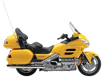
Honda GL1800 Trailer Hitch Installation Instructions

https://blogger.googleusercontent.com/img/b/R29vZ2xl/AVvXsEi2F5L-o9hY-ucjIhbkaH2sontYgfKWj_lQ4mVUGGjEA1HCFzvp3zeS8EJ9XnVXaX3ZZ_FZGhscsM8BlkF88NB96sXju4pVWQWpDTSKTVocHuqisFz54k_SOZTzbpYgZAMkegjXqPvkmNU/s400/HONDA+GOLDWING+1800cc+2009.png

Honda GL1800

Short Description
THE BUSHTEC GL1800 VERTICAL RECEIVER HITCH SYSTEM HAS BEEN EXCLUSIVELY DESIGNED FOR USE ONLY ON A STOCK HONDA GL1800. IT WILL NOT WORK ON ANY OTHER MOTORCYCLE. ANY MODIFICATION TO ANY PART OF THIS HITCH, INCLUDING BUT NOT LIMITED TO ALTERING THE SUPPLIED HARDWARE OR IMPROPER INSTALLATION COULD CAUSE INJURY OR DEATH AND IMMEDIATELY VOIDS ANY AND ALL WARRANTIES.

Website: www.bushtec.com
Filesize: 70kb
No of Page(s): 9

Content

1. Place the motorcycle on its centerstand on level ground. Remove the four bolts in the seat handles with a 6mm Allen head socket and remove the seat. NOTE: The rubber bushings inside the seat may fall out during removal; Make sure they are in place upon reassembly.
2. Remove both side covers.
3. Remove the (5) five bolts in the rear fender (license plate panel, between saddlebags) with a 5mm Allen head socket. Remove the rear fender. NOTE: The fifth bolt is behind the license plate.
4. Remove the (3) three bolts in the passenger floorboard holder cover with a 5mm Allen head socket. Remove the cover and repeat for other side.
5. Remove the (2) bolts in the rear saddlebag guard with a 12mm socket. Remove the saddlebag guard and repeat for other side.
6. Remove the bolt in the muffler hanger using a 12mm socket. Repeat for other side.
7. Loosen, but do not remove, the muffler clamps using a 6mm Allen head socket. Rotate the mufflers down slightly to allow the hitch hoop to slide between the mufflers and the saddlebags.


Get the file Download here

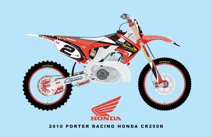
Honda CR 125/250R Installation Instruction manuals

https://blogger.googleusercontent.com/img/b/R29vZ2xl/AVvXsEjV15ZfGcgOWxvpuddBkovvIqB-GCTMaL9mZ98LeQggQzWrCnAq42tP0F5ZefkktqiKG5VlYAVbgkDCG2uQshOD8J2OegDt2SUCpBUmHnPebi2H8eKKHIOvDrtnIY0Wfc0nevkeUaO-894A/s730/2010+Porter+Honda+CR250R---1-13-10-printable.jpg

Honda CR 250R

Short Description
Note: The MSD Enhancer Ignition, PN KT4201, for the Honda CR 125 or CR 250R motorcycle is designed as a complete system. No part may be substituted with the stock ignition system.

Website: users.atw.hu
Filesize: 179kb
No of Page(s): 4

Content

The following explains some technical aspects of the Enhancer Ignition.
Battery: The battery is necessary to the operation of the Enhancer in two regards.
• The battery supplies voltage to the complex timing feature of the Enhancer.
• The Enhancer has a built in boost circuit that amplifies the spark energy at low rpm where the stock magneto is insufficient.
The MSD NiCad Battery pack, PN 4381, must be charged with the recommended battery charger or an MSD Fast Charger, PN 4385. The battery should be completely discharged before recharging. If a 7.2 Battery Charger is used, the recommended time for charging is seven hours. With the MSD Fast Charger the battery only needs to charge for one hour.


Get the file Download here

Kawasaki ER-5 Motorcycle Service Manual PDF

https://blogger.googleusercontent.com/img/b/R29vZ2xl/AVvXsEh31iHSZPzwJiiCyAyQfRDw16hOuuzzb9GqoUxTDvVWWuLPqyKe7aHObi4ucRBO7wwXXU0uW76t3LqhvhdLOSCGqGQvMfHNhp_3GgIb07KDjPw8Oqnb3AsOKZRmNZoYzpalK5YA41ecZmeK/s320/kawasakiEr5s-013-f.jpg


Short Description
This manual is designed primarily for use by trained mechanics in a properly equipped shop. However, it contains enough detail and basic information to make it useful to the owner who desires to perform his own basic maintenance and repair work. A basic knowledge of mechanics, the proper use of tools, and workshop procedures must be understood in order to carry out maintenance and repair satisfactorily. Whenever the owner has insufficient experience or doubts his ability to do the work, all adjustments, maintenance, and repair should be carried out only by qualified mechanics.

Website: users.atw.hu | Filesize: 7145kb
No of Page(s): 334

Content

Torque and Locking Agent
Tighten all bolts and nuts to the proper torque using an accurate torque wrench. An insufficiently tightened bolt or nut may become damaged or fall off, possibly resulting in damage to the motorcycle and injury to the rider. A bolt or nut which is overtightened may become damaged, strip an internal thread, or break and then fall out. The following table lists the tightening torque for the major bolts and nuts, and the parts requiring use of a non-permanent locking agent or liquid gasket. When checking the tightening torque of the bolts and nuts, first loosen the bolt or nut by half a turn and then tighten it to the specified torque.

Do not use compressed air on an assembled carburetor, or the floats may be crushed by the pressure, and the vacuum piston diaphragms may be damaged. Remove as many rubber or plastic parts from the carburetor as possible before cleaning the carburetor with a cleaning solution. This will prevent damage to or deterioration of the parts. The carburetor body has plastic parts that cannot be removed. Do not use a strong carburetor cleaning solution which could attack these parts; instead, use a mild, high flash-point cleaning solution safe for plastic parts. Do not use wire or any other hard instrument to clean carburetor parts, especially jets, as they may be damaged.


Get the file Download here

Instructions for Installing the Scootworks Preload Improvement Kit on Kawasaki 400/800

https://blogger.googleusercontent.com/img/b/R29vZ2xl/AVvXsEj-2JUUJLGL-xxKmfUiWwydO7vyTPXgfD4dveRd-7cw5jjIffuyEVeC5SfCT1i0RnFCD82bSemERAcxwBAq1aI8eXSbJBNa4436KesmF3srsWi6XiiPobiRrluNtE3G7d8WBZgR95PkKF3g/s1600/kawasaki-ninja-zx-rr-800cc-wallpapers.jpg


Short Description
This instruction booklet contains detailed steps for installing the rear suspension preload improvement kit on your Kawasaki 400/800 Standard (A model), Classic, or Drifter motorcycle. Please pay careful attention to the instructions regarding the disassembly and re-assembly of your motorcycle. If you have any questions concerning installation of your new Scootworks Preload Improvement Kit, please contact us via e-mail at support@scootworks.com. This will ensure you receive the most prompt and accurate reply.

Website: www.scootworks.com | Filesize: 129kb
No of Page(s): 11

Content

The shipping container and contents must be inspected by the purchaser for damage to goods immediately upon receipt of goods, and a claim must be filed with the carrier if damage is discovered. The purchaser must contact Scootworks within 24 hours from receipt of damaged goods to file a claim, and for further instructions.

1. Begin by removing both side compartment covers. The RH compartment cover requires the use of the ignition key for removal; the LH compartment cover is secured by a large Phillips screw. Once you’ve removed the LH cover, place the Phillips screw back into the hole in the frame (so you don’t misplace it) and set both covers aside. In many applications, you must remove the upper exhaust pipe (from the rear cylinder), and loosen the other pipe, to remove the inner parts of the RH side compartment cover (see below). Before attempting step #2 below, try step #3 first… depending on the brand of exhaust pipes you have, you may be able to avoid removal in step #2, if you are successful with step #3 first. Some brands of exhaust pipes provide access to the fasteners securing the RH side covers, eliminating the requirement to remove pipes for rear suspension access.
2. Remove the rear cylinder’s exhaust pipe. To do so, remove the two Allen nuts on the exhaust header, where it attaches to the engine, using an 8mm Allen wrench. Most often, this goes much more smoothly if you first spray the inside of the allen nut with a penetrating lubricant like WD-40. Remove the black acorn nut from the discharge end of the exhaust pipe (under the upper exhaust pipe, near the discharge end of the pipe) using a 12mm open-end wrench or socket. You’ll find a black metal spacer, through which the bolt goes, that is pressed through the rubber grommet. To avoid the potential of having it fall out unnoticed, remove it and place it aside with the nut. Remove the black bolt from the pipe just aft (to the rear) of where the pipe enlarges and above the pipe. This is actually a bracket that holds the two pipes together at a joint. Loosen the bolt using a 12mm socket, then slide it back onto the pipe you’re removing. Once you have the pipe off of the bike, the clamp will be loose. Be sure to keep it with the pipe, along with the rest of the removed parts. Loosen the pipe from the front cylinder BEFORE trying to remove the pipe from the rear cylinder. By loosening the header nuts on the pipe from the front cylinder, and removing the two black Allen bolts (6mm Allen wrench) under the forward pipe that attach it to the frame, you will be able to remove the rear pipe. There are more spacers in grommets where the 6mm Allen bolts secure the lower pipe to the frame (like those used in the rearmost connection of the rear cylinder’s pipe). These spacers will normally remain in the frame bracket, but if either is loose, remove them and store with the Allen bolts. If the pipe doesn’t come loose relatively easily, loosen the two top nuts on the black triangular metal bracket used to secure the pipes to the frame. With patience and care, however, you should be able to remove the pipe without loosening with the triangular bracket.


Get the file Download here

Kawasaki Vulcan VN800 Valve Adjustment Maintenance Procedure Instructions

https://blogger.googleusercontent.com/img/b/R29vZ2xl/AVvXsEhWfsmIh74UdntytchNujiQqfGb6stm6eSWFFllzGbT83FkmTma1Ly6pJGvFVVL9c44RPOKVhf4yfmckC3WGAyLM_EX7d0atFp_s4P3bFemXHmM5-V9ZNXFGdT7Ew-KYpPn7EkPDV9VGao/s320/Kawasaki_VN-800_Vulcan_Classic_2C_2004.jpg


Short Description
Tools Required: Torque wrench, 8, 10, 12 and 17mm 6 point sockets. Big Ass Phillips screwdriver. Set of METRIC feeler gauges. Digital METRIC caliper. You can pick up a caliper from Harbor Freight cheap and the feeler gauges from Snap-On for less then $5.00. Using them eliminates the potential for errors in conversions.

Website: www.kawasakimotorcycle.org | Filesize: 1058kb
No of Page(s): 14

Content
The subject in the accompanying pictures in a non-California version 2001 Vulcan VN800A with the “Cool Off” EPA removal mod performed. As we cannot address all the possible modifications that can be done, these instructions are written as if the bike is in stock form and you will have to make any adjustments necessary to accommodate mods to your specific bike. This is a very easy procedure that should not take more then four hours to perform with the actual valve adjustment only taking a few minutes but like most things, preparation is the key to success. As the engine internals will be open to the environment for a time, it is recommended this be done in doors. As the engine coolant must be drained, this is a very good time to flush the system and replace it as well.
Disassembly: There are shortcuts than can be taken but experience has shown me this is the best procedure to follow as Murphy’s law ensures you will do it all 99 times out of 100 anyway. The engine must be cold, i.e. not run for a good eight hours before starting this procedure. Remove the seat and fuel tank. Things should now look like as they do in figures VA01 and VA02. Our objective is to get things looking like figures VA03 and VA04. As you remove bolts and screws, put them back in after removing the component so they will not be lost and you won’t have to go looking for them during assembly. Using a 10mm socket, remove the two bolts holding the upper airbox chamber, pull the chamber up to remove and set aside. Remove the air filter cover with a 10mm socket. Remove the air filter. Using the same 10mm socket, remove the two chrome bolts that hold the airbox backing plate on. The backing plate does not need to be removed, just pull it loose from the carb and drop it down and turn clockwise until it is below the level of the valve covers. Use a wire tie or safety wire to secure it. Disconnect the carburetor float bowl vent tube from the carb and pull it along with the speedometer cable and fuel tank vents tube(s) back and down until they are completely out of the way of the rear valve cover. Even behind it. Cut all wire ties as needed to get all the tubes out of the way but remember where they were for assembly. Disconnect the coolant overflow tube from the back of the thermostat housing and pull it back and down until it is completely out of the way of the rear cylinder valve cover, even behind it. Now move to the left side of the bike and disconnect the EPA gold valve tube (or bypass) from the valve covers. Just let it lay down between the jugs with the fuel line. Pull the spark plug wires and get them out of the way. Remove the two large screws shown in figure VA05 and swing the choke cable over so that it lays between the jugs with the other lines. Set a drain pan under the bike and remove the 10mm coolant drain bolt show in figure VA06. Open the coolant fill cap on the top of the thermostat housing to speed draining of the coolant. Using a 10mm socket, remove the two bolts holding the thermostat housing to the frame shown in figure VA07. Using an 8mm socket, remove the bolt holding the Y coolant hose connector from the frame as shown in figure VA08. Using a Phillips screwdriver, loosen the hose clamps from the two coolant hoses attached to the top of the engine and disconnect the hoses. Swing the assembly up and position it on top of the frame as shown in figure VA07. We are now ready to remove the valve covers but I recommend using a rag and spray cleaner to clean any and all dirt from the frame and components above the valve covers to prevent it falling into the engine while the covers are off. Using the 10mm socket or wrench, remove the three chrome bolts on the top of both valve covers. Starting at the rear of the front valve cover, work a small flat screw driver between the valve cover and the gasket to break it loose and work around the cover until it is no longer stuck to the gasket. Now lift the cover straight up until it clears and remove to the left side of the bike. Note that the spark plug sleeve, shown in figure VA09 may stick preventing horizontal movement of the cover. If this happens, push it back down into the cylinder head with your finger through the spark plug hole while lifting up on the valve cover.


Get the file Download here

Kawasaki 800 Thunder Air Filter Kit Installation Instructions

https://blogger.googleusercontent.com/img/b/R29vZ2xl/AVvXsEgbR5YJMwwXQ5zyeFVkiqANg583oZsapS93RT0JCNupjIK8rhxCavKkz51eHh9fBAmzBbBlOtJ6XAjXfOPql6KzzFG3gmH0KotSw5Uba3qGfK0pf-R092dAQ3GlA64Osbh5zGy4NbD22S4/s400/2009-Kawasaki-Ninja-ZX-6R-2.jpg


Short Description
Congratulations on your purchase of the KAWASAKI 800 Thunder Air Filter Kit. We’re sure you’ll be pleased with the new level of performance you’ll experience. This kit should be installed on bikes with After Market Exhaust Pipes only and jetted, (not included). We recommend that an experienced mechanic perform this conversion. It is very helpful to have the appropriate Kawasaki service manual on hand for reference. Remember gasoline is extremely flammable and can be explosive under certain conditions. Work in a well-ventilated area and clean up any spills immediately. Check for leaks before riding.

Website: www.thundermfg.com | Filesize: 141kb
No of Page(s): 2

Content

1. Turn the fuel tap to the ON position.
2. Remove fuel hose and fuel tap vacuum hose.
3. Remove seat.
4. Remove Speedo Dash Plaque, lower center bolt only. Lift up and disconnect speedo cable and unplug electrical connections.
5. Remove fuel tank and bolts.
6. Remove two bolts on top of the Air Cleaner housing.
7. Remove Air Chrome Cover and filter.
8. Remove the Air Cleaner Housing from Carburetor. Disconnect the engine breather Hose and vacuum valve hose.
9. Remove carburetor holder plate.
10. Loosen the carburetor clamp screw.
11. See Shop Manual for complete removal.
12. Pull Carburetor forward and off.
13. Jetting and needle changes may be made with carburetor hanging loose.
14. Be sure to keep intake clean and covered. Keep dirt out of engine.
15. Drain float bowl - 3mm Allen - very bottom of carburetor
16. Remove float bowl 4 (#2 Phillips) let hang down.
17. Remove main jet. If Emulsion tube comes out use 8mm and flat tip to separate jet from emulsion tube.


Get the file Download here

Kawasaki 4stroke liquid-cooled v-twin gasoline engine Service Manual

http://3.bp.blogspot.com/_mxVVX-SZq6c/SPBLW-H5VnI/AAAAAAAAA8I/M2GJDXX_f_A/s400/kawasaki-2009-kfx-700-1.jpg


Short Description
This manual is designed primarily for use by trained mechanics in a properly equipped shop. However, it contains enough detail and basic information to make it useful to the owner who desires to perform his own basic maintenance and repair work. A basic knowledge of mechanics, the proper use of tools, and workshop procedures must be understood in order to carry out maintenance and repair satisfactorily. Whenever the owner has insufficient experience or doubts as to his ability to do the work, all adjustments, maintenance, and repair should be carried out only by qualified mechanics.

Website: www.mudbuddy.com | Filesize: 2391kb
No of Page(s): 154

Content
In order to perform the work efficiently and to avoid costly mistakes, read the text, thoroughly familiarize yourself with the procedures before starting work, and then do the work carefully in a clean area. Whenever special tools or equipment are specified, do not use makeshift tools or equipment. Precision measurements can only be made if the proper instruments are used, and the use of substitute tools may adversely affect safe operation. To get the longest life out of your engine:
• Follow the Periodic Maintenance Chart in the Service Manual.
• Be alert for problems and non-scheduled maintenance.
• Use proper tools and genuine Kawasaki engine parts. Genuine parts provided as spare parts are listed in the Parts Catalog.
• Follow the procedures in this manual carefully. Don’t take shortcuts.
• Remember to keep complete records of maintenance and repair with dates and any new parts installed.

Before starting to service the engine, carefully read the applicable section to eliminate unnecessary work. Photographs, diagrams, notes, cautions, warnings, and detailed descriptions have been included wherever necessary. Nevertheless, even a detailed account has limitations, a certain amount of basic knowledge is required for successful work.


Get the file Download here

Kawasaki Service Manual Fuel System

https://blogger.googleusercontent.com/img/b/R29vZ2xl/AVvXsEio6c38vWq4WXWKCudsdMPzV4pZ4NJ02mepTpet4zZ5P-x1VRsdd4J5z064sFtzD0sBfS6w2VRySk3yNemkZPe-0vV1-Tb0uUZGGuwLEpl4DPBD4z81pWl3Dond8sb_U0tbybcOmTi9dlsj/s640/kawasaki-ninja-250r.jpg


Short Description
Celan the carburetor in a well-ventilated area, and take care that there is no sparks or flame anywhere near the working area; this includes any appliance with a pilot light. Because of the danger of highly flammable liquids, do no use gasoline or low flash-point solvents to clean the carburetors.

Website: www.eaglefloorsolutions.com | Filesize: 4431kb
No of Page(s): 5

Content

- Remove: Air Cleaner and Related Parts (see Cleaner Body).
- Turn the fuel shut off valve to the OFF position.
- Drain the carburetor.
- Disconnect the fuel tube at the fuel inlet joint [A] of the carburetor.
- Disconnnect the solenoid valve lead terminal and remove the earth terminal (Electric Starter Model).
- Unhook the throttle link spring [B] at the throttle shaft lever [C] top end with a long nose plier.
- Unhook the throttle [D] and choke link rods [E] at he top ends of their arms while pull of the carburetor - FH451V, 500V, 531V.


Get the file Download here

KAWASAKI GOOD TIMES NEWS Striking Back

https://blogger.googleusercontent.com/img/b/R29vZ2xl/AVvXsEjbaG9iM3DHgxinUb_Ze_ko2wca7c75sy9FN_wFaGlTHPirlylbw5XDSaSLQSmEVQc9hXCdB4EC4yVuam1hVaNIRfMZ355izBFLPLUFQy-8kynOzpiVrnGINs0pxhXfgU_4JnFq8u3jveFA/s1600/Kawasaki_Z750_10.jpg


Short Description
IN AN OFF-ROAD market that is dominated by 450cc trail/enduro thumpers, the appearance of yet another machine in this class might barely raise any fuss at all. After all, how many 450s are there to choose from now? What is it – 10? So what’s the big deal about there being another new kid on the block? What’s different is that the latest arrival for the 450cc party isn’t another small-volume European brand bike that you’ll be lucky to see in magazine test reports, let alone in the flesh on a trail ride.

Website: www.kawasaki.com.au | Filesize: 415kb
No of Page(s): 3

Content
When a Japanese manufacturer presses the green light (get it… green light!) on a new model run, you can be sure there are years of development, stacks of research and an abundance of state of the art engineering tweaks that have gone into the mix. What’s more, it’s a sure bet the machine will be ultra-reliable, have performance to burn, handle sweetly, go like the wind and, quite likely, sell like hot cakes. Plus, you’ll be able to look closely at one on a dealer’s showroom fl oor, and perhaps even test ride one. Japanese manufacturers and their expansive dealer networks are also big enough to absorb, almost without question, any niggling warranty issues, should they crop up. So, don’t let the late (and early!) arrival of the 2008 model Kawasaki KLX450R put you off.


Get the file Download here

KAWASAKI PARTS & SERVICE MANUAL SUPREME LIQUID AND AIR COOLED

[2009+Kawasaki+Ninja+ZX-14+Monster+2.jpg]


Short Description
Read this manual and all other manuals pertaining to the Supreme carefully as they have safety, operating, assembly and maintenance instructions. Failure to do so could result in personal injury or equipment damage. Keep manuals in a safe place after operator and maintenance personnel have read them. Right and left sides are from the operator’s seat, facing forward.

Website: www.smithco.com | Filesize: 5674kb
No of Page(s): 114

Content

SPEED BOSS (KAWASAKI LIQUID COOLED)
Speed Boss allows the machine to operate at a proper speed while raking sand traps on golf courses. This speed boss has been factory set at an average speed of 3-4 mph(5-6.5 kph). The Speed Boss will only limit the speed while the rake is lowered into the operating position. The speed setting may be adjusted by removing the Yoke(A) from the Limiting Arm(B). Then loosen Jam Nut by ball fitting and Adjustment Rod(C). Turn Ball Joint clockwise to make the machine operate slower or turn counter clockwise to go faster. Tighten jam nut. Connect ball joint to limiting arm. Check to make sure nothing is binding and test drive to check desired speed.

WHEEL ‘CREEP’ ADJUSTMENT (KAWASAKI LIQUID COOLED)
‘Creep’ is when engine is running and hydrostatic transmission is in neutral, but due to inadequate alignment, wheels still move. Do the following procedures to stop this motion.
1. Lift up and support machine so all wheels are off the ground and can turn freely.
2. At rear of machine, on top of the hydrostatic transmission is the shift arm (A). Loosen bolts (B).
3. With engine running move stop (C) so it moves shift arm (A) to center and wheel creep stops.
4. Tighten all fasteners and test by using foot pedal linkage to see that the “creep” is removed.
5. Turn engine off and lower machine


Get the file Download here

Kawasaki KLR650 Fork Oil Check & Change

https://blogger.googleusercontent.com/img/b/R29vZ2xl/AVvXsEgUhgoLJRhAB9K__cnOOdq6fNiLNUBdOzNkYsFqPXmqLe-VbVMUsg0FWFzogZvvntZ_1a4iz2Fhy6EUtWrwfDIx3rZM89akT9_zI_yPVzo6ktUUAVqMUBMC3mabviGpCgLpO5fi1lu-C5oy/s400/kawasaki-KLR650_a_jpg.jpg


Short Description
This is a hobby website dedicated to the Kawasaki KLR650 motorcycle. I make no claim concerning the accuracy of the procedures, nor do I guarantee the success of any work done using them. All users of the material found here are advised that there is no real or implied warranty associated in any way with the website content, and that all content available here is for use at your own risk.

Website: www.klr650.marknet.us | Filesize: 119kb
No of Page(s): 5

Content

Front end off the ground. You absolutely must raise and block up the bike so the front wheel is off the ground if you want to remove and service both forks at once. (You can leave the wheel on, and do one side at a time, but I’ve never done it this way.)
* Remove the brake caliper & brake line mount from the left fork, and the speedometer cable mount from the right fork.
* Remove front wheel (See the note above)
* Loosen the fork caps by a few turns, but to avoid a possible mess leave them on until the tubes are off the bike.
* Loosen upper triple clamp fork pinch bolts. NOTE: You’ll probably have to insert a screw driver into the triple clamps to open them up a bit to help the tubes slide out. Mark or measure where your tubes are in the triple clamps so that when you reinstall them you put them back to the same height as they were before.


Get the file Download here

Kawasaki Recommended Service Manuals

https://blogger.googleusercontent.com/img/b/R29vZ2xl/AVvXsEgbR5YJMwwXQ5zyeFVkiqANg583oZsapS93RT0JCNupjIK8rhxCavKkz51eHh9fBAmzBbBlOtJ6XAjXfOPql6KzzFG3gmH0KotSw5Uba3qGfK0pf-R092dAQ3GlA64Osbh5zGy4NbD22S4/s400/2009-Kawasaki-Ninja-ZX-6R-2.jpg

Short Description
Kawasaki is pleased to provide a list of service tools and general service related supplies that are helpful for both field work and shop service work.

Website: www.kawasakiloaders.com | Filesize: 46kb
No of Page(s): 6

Content
Please notice that while this is not an exhaustive list of all necessary service tools and accessories, this is a very good start for shop tooling and needed supplies in additional to standard shop and hand tools. However, please remember that there may be some necessary Service Tools and supplies that are not on this list. …
The table below lists tools that are available from Kawasaki unless noted otherwise. The list is compiled by model number, from 50ZIV/ZIV-2 through 135ZIV-2, and ZV models are applicable as noted. This Service News will be updated when we receive more ZV information. This is not an exhaustive list of all needed tooling, but is a general guide to let the dealer know what is provided by Kawasaki, and tools that are good to obtain locally.


Get the file Download here

The Kawasaki EN500LTD Belt Drive Conversion Kit

[HM+KW1.jpeg]

Short Description
This instruction booklet contains detailed steps for installing the both the Classic and WideDrive belt drive conversion kits on your Kawasaki EN500LTD motorcycle. Please pay careful attention to the instructions regarding the unpacking and handling of your belt. The belt can be damaged if handled improperly. If you have any questions concerning installation of your belt drive, please contact us via e-mail at support@scootworks.com. This will ensure you receive the most prompt and accurate reply.

Website: www.scootworks.com | Filesize: 500kb
No of Page(s): 17

Content

BEGIN INSTALLATION
1. Begin by removing the engine sprocket cover. Use an 8mm socket to remove the four chrome bolts that hold the cover on. Be sure to hold on to the cover so it does not fall and get scratched up. Set the cover aside and screw the bolts back into the engine case so they don’t get lost. It is recommend you remove the left side, black plastic cover to prevent it from being scratched, using a large Phillips screwdriver. Before the front sprocket can be removed, the locking washer must be bent away from the nut that secures the sprocket. Using a screwdriver with a sharp point and a small hammer, bend the edges of the washer down flat against the front sprocket. The easiest way to fold down the washer sides that is securing the sprocket is to place a Flathead screwdriver (or something similar) in the joint between the washer and the sprocket nut, then tap the screwdriver with a light hammer. That will bend the washer side away from the locking nut on the sprocket. Then use a flat surface (like a brass drift pin or bar stock) and tap down the entire washer surface so it lies relatively flat against the outer surface of the sprocket. You might be able to get the nut off without flattening the washer all around but it’s far easier if you flatten it first (Fig. 01) [NOTE: All photos are located on pages 9-11 of this instruction manual. Refer to the (Fig #) for full details.]


Get the file Download here

Hydraulic Bed Lift Kit for the Kawasaki Mule

https://blogger.googleusercontent.com/img/b/R29vZ2xl/AVvXsEhn1e3kE-RU8R5nSZPT4Pq4QpItqR5ye_0l1SV9B_9VBMwwA1jvBVb2VOUWH1IFookb1HgsV8b9tphwP3LPpADNmdRaTwKOY-fBt8I-8u3mK9xnpA94na1R1GOmwah8SQ2o2walDoMB01I/s1600/Kawasaki-MineMadeParadise-017.jpg


Short Description
Thank you for selecting from Bed Lift Trans 4 Tough Stuff Products & Bridon Industries. For the easiest installation of the Bed Lift Kit, please follow the step by step sequence in this manual. Read and follow instructions / notations carefully in each step. Some covers and guards have been removed for illustrative / photographic purposes only in this manual.

Website: www.mulebedlift.com | Filesize: 1851kb
No of Page(s): 16

Content

Step 1
Identify these items supplied in the Bed Lift Kit:
1. Hydraulic pump with cylinder and bracket assembly. Note: Do Not disassemble lower bracket from
cylinder assembly.
2. Wiring harness, seat switch, toggle switch and decal.
3. Upper mounting bracket and fasteners.

Step 3
The installation steps # 4 thru 7 (installing lower bracket and cylinder assembly) and then steps # 10-15 (installing electrical cable) require working under the Mule in the center areas. A dealership may prefer to use an equipment hoist with open center access or front tire drive on ramps. We found raising the Mule approx 4 inches achieved comfortable working room for these noted steps. Pictured here is one option of a 4×4 wood block under each tire. However you choose to work on the under side of the Mule; the vehicle MUST be safely and fully supported on all four tires at all times.


Get the file Download here

1980 Suzuki GS850GT Stator Replacement

https://blogger.googleusercontent.com/img/b/R29vZ2xl/AVvXsEiUA8izvV2ACcgWBKZeHkk07P7hGcoUN8d0ZXtH_oY3AxD9rmjZZEKe0D4NYjjoxWNH8BhhqOmUgFB9AJWa3FTBoV29NoHebRFsBkdVeR4AGHuZNZY1YydsCQBwSZJgCt6w8zN-Yd6P3i4/s400/1980+Suzuki+GS850G.jpg

Short Description
Greetings to those of you who ride the classic GS series motorcycles from Suzuki. This documents my first experience replacing my stator. This procedure will be very similar for other GS series bikes, but be sure to refer to your bike’s service manual before proceeding. For a thorough background on the charging systems of the Suzuki GS series motorcycles, see “The Stator Papers” in the GSR Forum at http://www.thegsresources.com/garage/gs_statorfacts.htm . The GS Resources Forum is an excellent web community dedicated to keeping these classic bikes on the road. Visit or join at http://www.thegsresources.com .

Website: members.dslextreme.com | Filesize: 1142kb
No of Page(s): 16

Content
Let’s begin by disconnecting the positive terminal of the battery (or removing the battery altogether) and draining the oil. I happened to need an oil/filter change at the same time I was replacing my stator so the timing worked nicely. Some riders will just lean their bikes to the right, against something stable, so that when the left crankcase cover is removed no oil will drain out. Here is the left crankcase cover gasket. I’m holding it upside down, sorry. This is part number 477686-001.

Remove the left crankcase cover bolts (below). My bike still has the original phillips head bolts. They need a few taps from my impact driver to loosen them up. If I would’ve planned ahead they would be replaced with new hex head bolts. But alas, that will have to wait.
In the picture below, the cover is loose and hanging. At this point you may wish to just cut the stator wires but I chose to pull everything out intact.
If the magnetic force is strong enough, it may take a rubber mallet to encourage the case to come off. I also want to mention that the bolts are not all the same and must go back into their original holes. I started with the topmost bolt and removed them in a clockwise fashion, lined them up in order, so that I could put them back into their proper places during reassembly.

Get the file Download here

SUZUKI VX8OOL Service Manual

https://blogger.googleusercontent.com/img/b/R29vZ2xl/AVvXsEjTjgYGDsqqR4PpS_mOJ83ltV2ekOg_LX-UXBNa0c08qY5szMPQOO29zt0WB9YzpRhngjtbbPHBkfZW7DCxxTdzIA0jFM-FSyX0N68nLVru-mGfqo9xcji-S-Ip_4ZqGvNUfBV4Wz64e5s/s400/2010+Suzuki+GS500F+-+3.jpg

Short Description
The SUZUKI VX800 has been developed as a new generation motorcycle. It is packed with highly advanced design concepts including a V-2 engine, a liquid cooling system, a new highly efficient combustion system (TSCC), a fully transistorized ignition system and a shaft drive mechanism. Combined with precise control and easy handling the VX800 provides excellent performance and outstanding riding comfort.
This service manual has been produced primarily for experienced mechanics whose job is to inspect, adjust, repair and service SUZUKI motorcycles. Apprentice mechanics and do- ti- yourself mechanics, will also find this manual an extremely useful repair guide. This manual contains the most up-to-date information at the time of publication. The rights are reserved to update or make corrections to this manual at any time.

Website: www.vx800.net | Filesize: 990kb
No of Page(s): 14

Content

LIQUID AMOUNT OF WATER/COOLANT
Solution capacity (total): 1700 ml (I .8/l .5 US/Imp. qt)
For coolant mixture information, refer to cooling system section, page 5-2.
CAUTION:
Mixing of anti-freeze/coolant should be limited to 60%. Mixing beyond it would reduce its efficiency. If the anti-freeze/coolant mixing ratio is below 50%, rust inhabiting performance is greatly reduced. Be sure to mix it above 50% even though the atmospheric temperature does not go down to the freezing point.
BREAK-IN PROCEDURES
During manufacture only the best possible materials are used and all machined parts are finished to a very high standard but it is still necessary to allow the moving parts to “BREAK-IN” before subjecting the engine to maximum stresses. The future performance and reliability of the engine depends on the care and restraint exercise during its early life. The general rules are as follows.

Get the file Download here

SUZUKI SERVICE BULLETIN FUEL DELIVERY PIPE REPLACEMENT

https://blogger.googleusercontent.com/img/b/R29vZ2xl/AVvXsEgQv-_6CpNw_zJ6YldDYSSQiskgwABbT6Kz37ePbcJlSrqsSYdaMYnvcYetkTqEgnzwbPp0GZFjUEOxVGH7jxr1DtYub6AUyZNAucGxKrx41xUPe1CHDWcINQhVI-4PTEbGikSUm1OLdKI/s1600/suzuki_GSX_650F_2010_5.jpg

Short Description
Suzuki Motor Corporation has determined that on some affected motorcycles, the fuel hose that connects the two metal fuel delivery pipes mounted on the throttle body may have been clamped at a location on the pipes that is not completely round, which could allow fuel leakage to occur. In the presence of an ignition source, leaked fuel can cause a fire, presenting the risk of injury or death.

Website: www.m109riders.dk | Filesize: 366kb
No of Page(s): 7

Content
VERIFY THE UNIT REQUIRES MODIFICATION: Before performing the recall repair to a unit, first verify that the repair needs to be performed using one of the following methods; 1) Check the repair status by checking the Vehicle History in the Suzuki Connect Service Menu. If the repair needs to be performed, you will see the message “CAMPAIGN NOT YET PERFORMED” displayed and the fuel delivery pipe assembly will need to be replaced. Or 2) Inspect the unit for a punch mark located before the VIN 1 as indicated below. A punch mark indicates the recall repair has already been completed.

Get the file Download here