Showing posts with label Suzuki Manuals. Show all posts

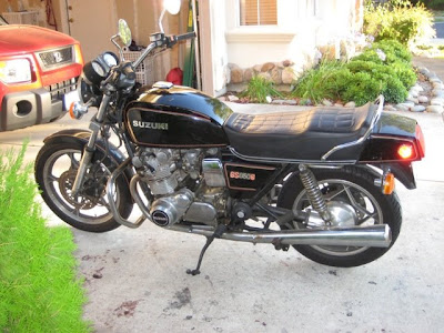
1980 Suzuki GS850GT Stator Replacement

https://blogger.googleusercontent.com/img/b/R29vZ2xl/AVvXsEiUA8izvV2ACcgWBKZeHkk07P7hGcoUN8d0ZXtH_oY3AxD9rmjZZEKe0D4NYjjoxWNH8BhhqOmUgFB9AJWa3FTBoV29NoHebRFsBkdVeR4AGHuZNZY1YydsCQBwSZJgCt6w8zN-Yd6P3i4/s400/1980+Suzuki+GS850G.jpg

Short Description
Greetings to those of you who ride the classic GS series motorcycles from Suzuki. This documents my first experience replacing my stator. This procedure will be very similar for other GS series bikes, but be sure to refer to your bike’s service manual before proceeding. For a thorough background on the charging systems of the Suzuki GS series motorcycles, see “The Stator Papers” in the GSR Forum at http://www.thegsresources.com/garage/gs_statorfacts.htm . The GS Resources Forum is an excellent web community dedicated to keeping these classic bikes on the road. Visit or join at http://www.thegsresources.com .

Website: members.dslextreme.com | Filesize: 1142kb
No of Page(s): 16

Content
Let’s begin by disconnecting the positive terminal of the battery (or removing the battery altogether) and draining the oil. I happened to need an oil/filter change at the same time I was replacing my stator so the timing worked nicely. Some riders will just lean their bikes to the right, against something stable, so that when the left crankcase cover is removed no oil will drain out. Here is the left crankcase cover gasket. I’m holding it upside down, sorry. This is part number 477686-001.

Remove the left crankcase cover bolts (below). My bike still has the original phillips head bolts. They need a few taps from my impact driver to loosen them up. If I would’ve planned ahead they would be replaced with new hex head bolts. But alas, that will have to wait.
In the picture below, the cover is loose and hanging. At this point you may wish to just cut the stator wires but I chose to pull everything out intact.
If the magnetic force is strong enough, it may take a rubber mallet to encourage the case to come off. I also want to mention that the bolts are not all the same and must go back into their original holes. I started with the topmost bolt and removed them in a clockwise fashion, lined them up in order, so that I could put them back into their proper places during reassembly.

Get the file Download here

SUZUKI VX8OOL Service Manual

https://blogger.googleusercontent.com/img/b/R29vZ2xl/AVvXsEjTjgYGDsqqR4PpS_mOJ83ltV2ekOg_LX-UXBNa0c08qY5szMPQOO29zt0WB9YzpRhngjtbbPHBkfZW7DCxxTdzIA0jFM-FSyX0N68nLVru-mGfqo9xcji-S-Ip_4ZqGvNUfBV4Wz64e5s/s400/2010+Suzuki+GS500F+-+3.jpg

Short Description
The SUZUKI VX800 has been developed as a new generation motorcycle. It is packed with highly advanced design concepts including a V-2 engine, a liquid cooling system, a new highly efficient combustion system (TSCC), a fully transistorized ignition system and a shaft drive mechanism. Combined with precise control and easy handling the VX800 provides excellent performance and outstanding riding comfort.
This service manual has been produced primarily for experienced mechanics whose job is to inspect, adjust, repair and service SUZUKI motorcycles. Apprentice mechanics and do- ti- yourself mechanics, will also find this manual an extremely useful repair guide. This manual contains the most up-to-date information at the time of publication. The rights are reserved to update or make corrections to this manual at any time.

Website: www.vx800.net | Filesize: 990kb
No of Page(s): 14

Content

LIQUID AMOUNT OF WATER/COOLANT
Solution capacity (total): 1700 ml (I .8/l .5 US/Imp. qt)
For coolant mixture information, refer to cooling system section, page 5-2.
CAUTION:
Mixing of anti-freeze/coolant should be limited to 60%. Mixing beyond it would reduce its efficiency. If the anti-freeze/coolant mixing ratio is below 50%, rust inhabiting performance is greatly reduced. Be sure to mix it above 50% even though the atmospheric temperature does not go down to the freezing point.
BREAK-IN PROCEDURES
During manufacture only the best possible materials are used and all machined parts are finished to a very high standard but it is still necessary to allow the moving parts to “BREAK-IN” before subjecting the engine to maximum stresses. The future performance and reliability of the engine depends on the care and restraint exercise during its early life. The general rules are as follows.

Get the file Download here

SUZUKI SERVICE BULLETIN FUEL DELIVERY PIPE REPLACEMENT

https://blogger.googleusercontent.com/img/b/R29vZ2xl/AVvXsEgQv-_6CpNw_zJ6YldDYSSQiskgwABbT6Kz37ePbcJlSrqsSYdaMYnvcYetkTqEgnzwbPp0GZFjUEOxVGH7jxr1DtYub6AUyZNAucGxKrx41xUPe1CHDWcINQhVI-4PTEbGikSUm1OLdKI/s1600/suzuki_GSX_650F_2010_5.jpg

Short Description
Suzuki Motor Corporation has determined that on some affected motorcycles, the fuel hose that connects the two metal fuel delivery pipes mounted on the throttle body may have been clamped at a location on the pipes that is not completely round, which could allow fuel leakage to occur. In the presence of an ignition source, leaked fuel can cause a fire, presenting the risk of injury or death.

Website: www.m109riders.dk | Filesize: 366kb
No of Page(s): 7

Content
VERIFY THE UNIT REQUIRES MODIFICATION: Before performing the recall repair to a unit, first verify that the repair needs to be performed using one of the following methods; 1) Check the repair status by checking the Vehicle History in the Suzuki Connect Service Menu. If the repair needs to be performed, you will see the message “CAMPAIGN NOT YET PERFORMED” displayed and the fuel delivery pipe assembly will need to be replaced. Or 2) Inspect the unit for a punch mark located before the VIN 1 as indicated below. A punch mark indicates the recall repair has already been completed.

Get the file Download here

SUZUKI LTR450 Fuelpak Installation Instruction Manuals

https://blogger.googleusercontent.com/img/b/R29vZ2xl/AVvXsEgYO_jcGaH4pqO7bFxZr5HZlRei9nYMyqPEtF7qjCGZQHid326XIAm9SXHCtHibG73K5Glkt2x5tG3FsUkbY79PZz4ccQfn78m398kE322PSbr1Ltv9e_K4FCBMgIv-J3aCAWDFL-1zQUNS/s1600/2009-Suzuki-QuadRacerR450-LTR450Z-LimitedEditionb.jpg

Short Description
To achieve the optimum performance from your application, it is recommended that you install a high performance air filter in conjunction with this unit. Fuelpak will be installed in-line with the factory injector wiring harness and the throttle position sensor. The unit will be mounted under the seat.

Website: www.fuelpakfi.com | Filesize: 216kb
No of Page(s): 2

Content

(Important Note): Fuelpak maps for the LTR450 were created with a White Brothers Power Pro performance module installed. The included Power Pro unit must be used in conjunction with the Fuelpak for proper function. Failure to do so will result in poor performance and may cause engine damage.
1. Be sure that key is in the off position, then remove seat.
2. Referring to figure 1, remove (4) push pins and (1) 10mm bolt. Repeat for opposite side. Push pins that are accessible from the back can be popped out by pushing on the pin from the back side. Push pins with flanged pin heads can be gently pried up with a slotted screwdriver.
3. Remove fuel cap and tank cover. Reinstall fuel cap.
4. Clean Fuelpak mounting location with alcohol and allow to dry. Referring to figure 2, mount Fuelpak as shown with supplied Velcro. Route harness as shown, between airbox and subframe, and underneath subframe cross brace.Gently pull up and out on subframe side cover and attach harness to subframe with included zip ties. Ensure that harness is not running over black rubber strip behind airbox.

Get the file Download here

SUZUKI DF2.5 2.5-Horsepower 4-Stroke Portable Outboard Motor

http://4.bp.blogspot.com/_2SF5i8wA0eg/StvWx5VTRzI/AAAAAAAAAPc/B3-3_lRWDE8/s400/2009-Suzuki-V-Strom650-DL650a-small.jpg

Short Description
AlwAll new for 2006, Suzuki is pleased to introduce the DF2.5 portable outboard — the smallest Suzuki 4-stroke to date. Weighing just 30 pounds, the DF2.5 is the lightest Suzuki 4-stroke motor ever built. And Suzuki is also proud to note that the DF2.5 meets the rigorous EPA 2006 and CARB 3-Star Ultra Low emissions standards.

Website: www.suzukimarine.pl | Filesize: 1391kb
No of Page(s): 2

Content

Engine
A 2.5 HP single cylinder OHV 4-stroke engine, with 4.15 cu. in. displacement, generates plenty of power for small tenders and inflatables. It features easy-to-pull recoil starting with Suzuki Pointless Electronic Ignition. No battery is required for this remarkably simple and reliable system.
The DF2.5 engine runs quietly and smoothly, and is water-cooled, which promotes improved dependability. Its integrated fuel tank holds nearly a quart of gas and it has an estimated run time of almost an hour on a full tank. It is easy to check oil levels with the oil level indicator located on the port side. And you never have to mix oil and gas.

Tilt And Carrying Handle
aWhen you need to tilt the DF2.5 engine up, there is an easy-to-grip integrated handle located at the back of the engine cowling within convenient reach. And there are four tilt pin settings designed to match your individual boat and the prevailing conditions. The fuel On/Off switch is on the starboard side, for easy access whether you’re starting or finishing engine operation. (Note: Always turn off fuel flow when not in use.) Off the transom, the DF2.5 is balanced, lightweight and easy to manage, due to its large grip carrying handle. A special bracket extends when the engine is tilted up to prevent it from laying over on its side.

Get the file Download here

SUZUKI GSX250F Workshop Manual PDF

http://4.bp.blogspot.com/_q_1lsEUCFpA/Ss4apczuxeI/AAAAAAAAACU/vq9mzouhPvs/s320/Suzuki-GSX-250F.jpg

Short Description
The SUZUKI GSX250F has been developed as a new generation motorcycle to the GS-models. it is packed with highly advanced design concepts includng a new highly efficient combustion system, a fully transistorized ignition system and an improved link type rear suspension. Combined with precise control and easy handling the GSX250F provides excellent performance and outstanding riding comfort.

Website: www.dethlefsens.dk | Filesize: 7031kb
No of Page(s): 229

Content

COOLING SYSTEM
- Loosen the screw and remove the radiator cap 1.
- Remove the drain plug 2 and disconnect the hose, and drain coolant thoroughly while holding the mororcycle upright.
WARNING:
Do not open the radiator cap when the engine is hot, as you may be injured by escaping hot liquid or vapor.
Cooling solution may be harmful if swallowed or if it comes in contact with skin or eyes. If cooling solutions gets into the eyes or in contact with the skin, it should be flushed thoroughly with plenty of water. If swallowed, induce vomitting and call physician immediately.
- Flush the radiator with fresh water.
- Tighten the drain plug securely.
- Fill the specified coolant up to the radiator inlet hole.

Get the file Download here
Instructions for 240 Suzuki Hayabusa Swingarm Installation

http://3.bp.blogspot.com/_D_0yuZhzSfE/SYPYiUtUvUI/AAAAAAAAAFw/2GvFvmik9Q8/s400/2009-Suzuki-HayabusaGSX1300Ra-small.jpg

Short Description
An advanced degree of mechanical skill is required to properly install this kit. If after reading these instructions you have any doubts, we strongly recommend that you have a professional install it for you. If you install the kit yourself, we recommend that you also use the applicable shop manual for your motorcycle. This kit involves significant alterations of your motorcycle and may void your factory warranty.

Website: rccomponents.com | Filesize: 517kb
No of Page(s): 10

Content

1.) Stock Component Removal
To begin installing this kit it is necessary to raise the rear end of the bike using a suitable hoist. Be sure to keep the bike centered on the front wheel to keep the bike from tipping over. Once you have the bike lifted and properly secured, begin with the removal of the following stock components (For detailed information on the removal of these parts, please consult you factory manual):
1.) Both mufflers
2.) Left side and lower body panels
3.) Voltage regulator (08 model only)
4.) Front sprocket cover
5.) Chain
6.) Rear Axel, wheel and brake assembly
7.) Pivot tube and swingarm
2.) New Swingarm Installation
A. Begin installation by moving your new swingarm into position. Once you have the swingarm in position reinsert the pivot tube to hold it in place.
B. Next, you will want to reattach the shocks to the underside of the swingarm.

Get the file Download here

Suzuki VX800 Owners Manual

https://blogger.googleusercontent.com/img/b/R29vZ2xl/AVvXsEj09J85jONwGzEoY6JO7pjGj26oXlQIXct0Zkh7QXJ4oIB77bgc6IwqE0K4jToREPOV9xgmCQHat13yD4EoFPjpoICfwQG_GB3a5Yi1ysQAAU3wztSte_n6AbzSr8IfMq2NITUIUui4k78/s400/Stiege025.JPG

Short Description
Your motorcycle and this owner’s manual have been desinged by people like you who enjoy motorcycling. People become motocyclists for many reasons. For starters, street riding is fun and invigorating. But no mtter why you became a motorcyclist, or how experienced you are, you will eventually face some challenging situations.

Website: www.vx800.net | Filesize: 7912kb
No of Page(s): 40

Content

FUEL, OIL, AND ENGINE COLLANT RECOMMENDATION
FUEL
Suzuki highly recommends that you use alcohol-free unleasded gasoline whenever possible, with a minimum pump octane rating of 87 ((R + M)/2 method) or 91 octane (Research Method). In some areas, the only fuels that are available are oxygenated fuels. Onygenated fuels which meet the minimum octane requirement and the requirements described below may be used in your motorcycle without jeopardizing the New Vechile Limited Warranty or the Emission Control System Warranty.
NOTE: Oxygenated fuels are fuels which contain oxygen-carring additives such as MTBE or alcohol.
Gasoline Containing MTBE
Unleaded gasoline containing MTBE (Methyl Tertiary Butyl Ether) may be used in your motorcycle if the MTBE content is not greater than 15%. This onygenated fuel does not contain alcohol.
Gasoline/Ethanol Blends
Blends of unleaded gasoline and ethanol (grain alcohol), also known as gasohol, may be used in your vehicle if the ethanol content is not gereater than 10%.
Gasoline/Methanol Bleads
Avoid using blends of unleaded gasoline and methanol (wood alcohol) whenever possible. DO NOT USE fuels containing more than 5% methanol under any circumstances. Fuel system damaage or motorcycle performance problems resulting from the use of such fuels are not responsibility of Suzuki and may not be covered under the New Vehicle Limited Warranty or the Emission Control System Warranty.
Fuel containing 5% or less methanol may be suitable for use in your motorcycle if they contain cosolvents and corrosion inhibitors.

Get the file Download here

Suzuki Adjustable Cam Sprocket Instructions

https://blogger.googleusercontent.com/img/b/R29vZ2xl/AVvXsEgDGbIkuDH7BODfoU1nmCJlVezcdBmyw4-H2713blkhLrEozvGqLxnLLachBzme0Q-1Mx9injTsk5cM5763JaczUNRMJU8PqD0S7msAZP7Ay5AKejnUtZoCr_rbeGqxGF_TRQVNnKrR-AFe/s1600/2010-Suzuki-GSX-R-1000Z-25th-Anniversary-Edition.jpg

Short Description
SA-S-750 (GSXR-600 & GSXR-750) Early
SA-S-1300 (GSX1300 R)
The GSXR has a ball bearing behind each cam sprocket. Press the original sprocket off but leave the bearing on. You’ll notice that a line has been stamped on the end of each camshaft at the factory. Line up one of the adapter’s 6mm threaded holes with the line and press the adapter on. Caution: make sure you press the adapter on the right way (with the larger of the two steps facing outwards). Make sure you are pressing the adapter on squarely to the cam. When pressing on an adapter, support the camshaft securely and squarely by the flange behind the ball bearing.

Website: www.mpsracing.com | Filesize: 108kb
No of Page(s): 1

Content

Cam Sprocket #SA-S-752 Late model, 2000+ GSXR-600, 750, & 1000
You will need to press off the old sprocket and press on the new sprocket adapter provided. Please note that a line has been stamped on the end of each camshaft at the factory. Take a good look at the end of the cam sprocket and the timing marks before you press off the old sprocket. Make yourself a sketch for reference if you do not have a factory repair manual. You may also want to check the stock cam location with a -degree wheel. You will need to degree in your cam to the new settings after you install the adjustable sprockets.

Get the file Download here

Suzuki Samurai 1985-1989 Fastback Top Installation Instructions and Owner Service Manual

http://3.bp.blogspot.com/_7g_Bxg6_7IE/SQH0iVgC2BI/AAAAAAAABsA/deyeYFwGfUs/s320/Samurai.jpg

Short Description
Congratulations on your purchasing decision. Bestop designed the Convertible Top to give you years of dependability and performance with proper care.

This product is designed to enhance the appearance of the vehicle and to shield the occupants from ordinary weather conditions. Do not rely in any way on the components of this product to contain occupants within the vehicle, or to protect against injury or death in the event of an accident. This product will not protect the occupants from falling objects. Never operate vehicle in excess of manufacturer’s specifications.

Website: www.bestop.com | Filesize: 384kb
No of Page(s): 5

Content

Your top is made of the finest materials available. To keep it looking new and for the maximum possible wear, it will need periodic cleaning and maintenance.

Washing: The top fabric should be washed often using soap, warm water and a soft bristle brush. Rinse with clear water to remove all traces of soap.
Windows: Keep windows clean to avoid scratching. DO NOT use a brush on the windows! Wash with a watersoaked cloth or sponge and a mild dishwashing detergent. NEVER WIPE THE WINDOWS WHEN THEY ARE DRY. Be careful when cleaning snow or frost from the vinyl windows since they are easily scratched and may crack at low temperatures. DO NOT roll the sides or rear curtain in cold weather. The windows become stiff and will crack.
Zippers: Keeping the zipper cleaned and lubricated with a silicone lubricant will help prevent damage and keep the zippers in a smooth working condition. If a zipper opens behind the slider, the slider may have been spread apart. This problem can usually be repaired by using an ordinary pair of pliers to bring the sides back into parallel. Return slider to the end of the zipper in the normal Open position. Squeeze lightly at first and test the zipper. If the zipper continues to remain open squeeze more firmly with the pliers and try the zipper again. Repeat this procedure until the zipper operates correctly.

Get the file Download here

Suzuki King Quad 700 EFI Control Box Instructions Manual

http://4.bp.blogspot.com/_5CNFBJhHzCw/Sa_LvB9aH2I/AAAAAAAAf48/dF89JbR6OrU/s400/suzuki-kingquad-750axi-rockstar-edition-atv-2009.jpg

Short Description
The Boondocker Control Box connects between the engine’s ECU (Electronic Control Unit) and the fuel injectors. It does not reprogram or communicate with the ECU. It only modifies the existing signals sent from the ECU to the fuel injectors. By modifying only these signals, it is possible to make fuel changes while keeping the stock fuel map. This means the ECU can still compensate for engine speed, throttle position, barometric pressure, engine temperature, air temperature, etc.

Website: www.exhaustgas.com | Filesize: 908kb
No of Page(s): 10

Content

IMPORTANT NOTES:
Note 1: Avoid exposing the Control Box to environments where static charges may exist. For example, quickly removing a cover from the atv in a dry environment can create a static spark that will damage the box.
Note 2: The Control Box is sealed – do not take it apart or it will no longer be sealed. The Control Box is designed to be splash-proof. Do not submerge or subject the box to high-pressure spray. During long periods of non-use it is recommended that you do not leave the control box exposed to the elements.
Note3: We recommend using Dielectric Grease on all connections to help prevent corrosion on the terminals.

II. Wiring:
A. Injector wiring:
The Control Box EFI wiring harness plugs in between the stock injector connector and the injector itself. Starting by unplugging the factory connector from the fuel injector. Then plug the boondocker injection harness on to the fuel injector and into the factory connector. The white connector connects to the Control Box. You can locate the fuel injector by removing front plastics and fuel tank

Get the file Download here

Download How To Change Your Oil and Filter-Suzuki GS

https://blogger.googleusercontent.com/img/b/R29vZ2xl/AVvXsEj6pVgMWnyBvEmSAdjGa5dTcI3j-6v7vJSKoUBjF_dMW0bARYaojKgLgUC0hnbKWV6HO0AudanPhrVyRIsBF5IZECgHhqjSujXNywMx3ZL7iypn872lvEMs-gx-5dvTbYqyTkuxs1-uECs/s320/suzuki-gs500f.jpg

Short Description
By popular demand I have undertaken the task of documenting one of my recent oil and filter changes on my GS850GT. I hope you find this helpful as you care for and maintain your classic Suzuki GS series motorcycle. This procedure will be similar for many of the GS series bikes. However, you are encouraged to refer to your owner’s manual, Suzuki Shop manual, Clymer, Haynes, etc, for further information specific to your motorcycle.

Website: www.cycleorings.com | Filesize: 640kb
No of Page(s): 10

Content
This guide assumes that you have all the necessary supplies and parts. Don’t ask me which oil to use! This is a hotly debated subject on the GSR Forum. Whether you use the expensive “motorcycle specific” oil or cheap Rotella oil, it is the thought of many that as long as you change it frequently (at least every 1500 to 2000 miles) you can use just about any kind of motor oil. Personally, I’ve been using the Castol Syntec Blend 20w50 in the summer and 10w40 in winter. The oil filter itself is common to a lot of Suzuki bikes, from the GS425 on up to the GS1100. Again there are many opinions as to which filter to use and many opinions as to quality; Fram (CH6001), Purolator (ML16800), Napa/Wix (24931), HiFlo Filtro (HF133), K&N (KH133), STP (rebranded Fram), EMGO (10-29800), Suzuki (16510-45040), etc. Personally, I buy filters from an ebay store (Breezers Motorcycle Parts) in lots of 5 that include the O-rings. Sometimes they have Suzuki OEM filters, sometimes it’s HiFlo Filtro. I have no affiliation with Breezers other than I’m a satisfied customer. I feel the same way about filters as I do oil, change it often enough (I change my filter at every oil change) and just about any one will get the job done. If you tend to abuse your oil and go longer between changes, then you may wish to buy the more expensive, higher quality oils and filters. Now let’s get down to business…
I like working on a cold bike. Many riders will pull the drain plug when the bike is warm. Warm oil flows more easily and may carry out more contaminants. Then you can come back after the pipes have cooled to finish the job. Have four quarts of oil, filter and O-ring at the ready. You won’t need all that oil right away but you’ll have extra if you need to top off your oil level between changes. Put your bike on the center stand, unless you’re lucky enough to have a lift.

Get the file Download here

PROCEDURE NOTES SUZUKI DL650 THROTTLE-BODY SYNCHRONISATION

https://blogger.googleusercontent.com/img/b/R29vZ2xl/AVvXsEgyjSzkPeP4oBM5hyphenhyphenaW-rZT_evm_a0MhH2Y_AZu4ollt9XetjtH_q9DL4yp8QXenTtGo_ldSRzTCXd8P9X6TKoXsAeBZvKY1MHUKtPlU7uCbpds5kU32FjlkVOOHkAlGfyx9NoalzwjHis/s1600/suzuki_DL650_V-Strom_2010_1.jpg

Short Description
The DL650 has two throttle bodies, one for each cylinder. These throttle bodies meter the air that is delivered to each cylinder for fuel combustion. To ensure smooth operation of the bike’s engine, these throttle bodies must be synchronised so that each cylinder receives the same amount of combustion air for each power stroke.

Website: www.tpgtex.com | Filesize: 401kb
No of Page(s): 6

Content

5. PREPARATION
The bike’s Suzuki service manual calls for the bike’s air box to be removed before synchronising the throttle bodies. From experience, this has not been found necessary, although it does give easier access to the throttle body take-off pipes for the manometer. Many believe the effort is not worth it. For these notes, the air box is not removed.
It is recommend (but not mandatory) that you fit new spark plugs and a clean air filter (if air box is left in place) to the bike before proceeding with the throttle body synchronisation. See the Owners Manual for fitting these items.
• Remove the bike’s seat (see Owners Manual).
• Remove the left-hand and right-hand black plastic side covers (see Owners Manual).
• Raise the fuel tank (see Owners Manual) and support on its prop.
Note: To remove the black plastic “press studs” use the smallest hex key in the tool kit to press in the centre pin of the stud one click (about 2mm). You should then be able to pull the stud (with pin) straight out. Be careful not to loose the pin.
• Disconnect the IAP sensor hose from its connection on the air box (see fig. 1).

Get the file Download here

SUZUKI / GSX-R600/750 / 2006-2007 Slip-On System Installation

https://blogger.googleusercontent.com/img/b/R29vZ2xl/AVvXsEjlEPtRjcs0Q3ccmQEvIOpPpsR3ce1-sbi2rlj40KUUpUOCaPLC0C1HelyLrx5aD3nR5Asof-ACZnphcFWa65932xhHjNVMDSr1CRUYk8uMmBa4V_TGou57RF0pXOhcWCLDOzGlEs1VYtv5/s1600/suzuki_GSX-R_750_2006_01.jpg

Short Description
Installation Instructions
1 After bike is cool make sure the bike is secured before beginning the installation.
2 Remove the right side lower fairing bolts and pull the fairing out from the push pin/rubber connector.
3 Fully loosen the muffler clamp from the header collector.
4 Remove the 3 muffler mounting bolts (2 on the right side, 1 on the left side).

Website: www.leveloneracing.com | Filesize: 1028kb
No of Page(s): 5

Content
5 Carefully remove the stock muffler and place in a safe location.
6 Apply a small amount of high temperature silicone (such as Permatex Ultra Black) to the inside of the exhaust inlet. Attach the LOR exhaust canister to the slip-on tube adapter with the spring tabs aligned (make sure your hands are protected with a pair of gloves in case the tubes slip). You may have to squeeze the midpipe adapter tube to fit into the exhaust inlet as the mandrel bends may become slightly out of round due to a cut near the bend (the tube will take form once connected). Slide the canister all the way until the slip-on adapter seats fully against the exhaust inlet. Wipe off any excess silicone. Place each spring over the exhaust side spring tabs and use the spring tool to pull the springs over the adapter spring tabs. Both springs must be secured for proper installation.
7 Apply a small amount of high temperature silicone sealer (such as Permatex Ultra Black) to the inside (inlet side) of the slip-on adapter. Slide the low profile barrel clamp over the LevelOne Adapter pipe. Slide the slip-on adapter pipe over the stock header collector. Do not fully tighten the barrel clamp.
8 Place the round canister clamp with the rubber gasket over the rear of the exhaust and slide to the angle bracket clamp location (Follow the instructions for the hanger conversion located at the end of this manual). Follow the clamp setup (shown in figure 1a or 2a) based on your sleeve type. Do not fully tighten as you will need to adjust the system for a perfect fit.

Get the file Download here

SUZUKI 800 VOLUSIA Adaptor Kit Installation Instructions

http://2.bp.blogspot.com/_st_y1LRiUIg/Sb-Tib7PmmI/AAAAAAAAB7M/cDEESDklkgk/s400/Suzuki%2BIntruder%2BM1800R%2B2,%2B2009.jpg

Short Description
Congratulations on your purchase of the SUZUKI 800 VOLUSIA Adaptor Kit. We’re sure you’ll be pleased with the new level of performance you’ll experience. This kit should be installed on bikes with After Market Exhaust Pipes only and jetted, (not included). We recommend that an experienced mechanic perform this conversion. Use the appropriate Suzuki service manual for reference to complete jetting of carbs.
Remember, gasoline is extremely flammable and can be explosive under certain conditions. Work in a well-ventilated area and clean up any spills immediately. Check for leaks before riding.

Website: www.thundermfg.com | Filesize: 123kb
No of Page(s): 2

Content

Tornado or Hurricane Installation:
Use instructions included with the adaptor for your bike and install the adaptor first. With your adaptor installed now attach the Hurricane – Tornado adaptor plate using the (2) - 6 X 16 flat head cap screws included with the adaptor. Now use the (3) ¼ -20 X ½” chrome socket heads included with the air kit to bolt on the Tornado or Hurricane.
Please note that the Tornado filter is very snug. Filter should be at room temperature or warmer. The rubber does not expand when cold. Apply Windex or similar to Tunnel and inside of filter flange. Be careful when putting filter on so not to wrinkle pleats. It is recommended that you hold filter light but firm, at large end with flange
Hyper Charger Installation: Use the instructions step 1 – 15 included with the adaptor. With your HC adaptor installed now attach the Hyper Charger using the (3) m6-1 x 10 socket head cap screws included with the HC adaptor and enjoy.
Skull Installation: Use the instructions steps 1 – 15 included with the adaptor. Next drill out the threads from the top of the skull backing plate – use ¼ drill bit (not provided). See image pictured. Now use the bolts supplied to attach the skull backing plate to the thunder adaptor.

Get the file Download here

Adjustable foot peg kit for Suzuki GSX-R1000 Users Service Manual

https://blogger.googleusercontent.com/img/b/R29vZ2xl/AVvXsEiE09Oyzfnzras9VPcSJmbSvDAntQkpwpOVPnPWMC4-LCFTw1xOlPTzy5j3cvlcdEcVE4BzH8IFwv9xZ1uahi1MSs3mgh7bvpdkb6CW_ejHcy72NXrkkjR4yqumkLGLrgiSSFsu54aLAZlA/s320/SuzukiGsxr1000.jpeg

Short Description
To prevent burns, work must be conducted only after the engine has properly cooled down. To ensure the bike does not fall over as you work on it, make sure it is stood on level ground. During the installation of the kit make sure that all parts are securely tightened to prevent from falling plate or loose master-cylinder. Pay special attention to the brake system, errors can cause serious injury. After installation, make sure that the parts of the kit are not touching other parts. Some parts are loosely tightened at the time of shipment. Please make sure all parts are securely tightened during the installation.

Website: tiforce.com | Filesize: 101kb
No of Page(s): 3

Content
Vibration can loosen the bolts while riding. Please regularly check all parts are securely tightened. Especially after any fall accident, please make a thorough check. This product is for standard motorbikes and those with our exhaust installed. There is possibility that this product cannot be installed when the motorbike has another non-standard exhaust, swing arm or frame, etc. Do not dismantle or alter our product. (It causes loss of function, and could cause fatal accidents.) Please note we cannot accept return of a kit when it has been illegally used or installed. If the motorbike has had a fall and its frame has been damaged, the installation of the kit may not be possible. In case of accident and damage to our product, please do not use. The broken parts may cause harm to the rider. The accident might cause the exhaust to fall off the motorbike and thus fatal accident or injury.

Get the file Download here

Suzuki 03-04 GSX-R1000 TiForce exhaust system

https://blogger.googleusercontent.com/img/b/R29vZ2xl/AVvXsEhKB-lSdorheBceYYPSa_Q43akS0SPeI7kLEmJ_T7joh_fTIsL67PJKuqNjvrSm8sQIUtmhsbPp-GLnKEMBgbvpmmvyNqTn2ubWjXdP8e8dc9jfM_0qisFbw2Wmq387u3I8zqgBr3SdXF7f/s1600/suzuki_GSX-R_1000_2005_3.jpg

Short Description
Thank you for selecting and purchasing a TiForce exhaust system for your ‘ 03-’04 GSX-R1000. TiForce is the world’s finest titanium exhaust system available today. Please read the following instructions and materials to fully familiarize you with new exhaust system before getting started.

Website: www.tiforce.com | Filesize: 408kb
No of Page(s): 4

Content

1. Detach the seat, battery, under cowling, tail winker and passenger foot peg.
2. Use standard rod to lift the fuel tank and detach the connector of the exhaust devise servomotor. (Failure to detach the connector and turn on the main switch, serious damage may occur to the servomotor.)(*See Photo. 1) Detach the standard silencer and wire for the device.
3. Release the coolant and detach the oil cooler. Detach the standard exhaust pipes after free the oil cooler.
4. Attach an enclosed exhaust pipe to the engine and tighten enough to keep from slipping out of place. (Cylinder number is 1,2,3 and 4 from the engine right side) *Suggest using new gasket in order to prevent leaking the exhaust. *Use the standard flange nut and tighten by hand.
5. Attach the joint pipe followed by the tail pipe. Jiggle it and attach the springs. *Make sure to push into the joint pipe from the right body side to the oil pan. Failure to push into the joint pipe may touch the under cowling.
6. Attach the enclosed silencer stay using by Collar A and Bolt (M8-50mm) to the position of the passengers foot peg of the silencer side. (See Fig. 1) *For the passenger foot peg users, use collar B and Bolt (M8-110mm).
7. Push silencer into the tail pipe, put the springs, silencer rubber band, band and silencer stay. (Make sure to use rubbered springs to the upper side of the silencer joint.) (M6 x 20mm x 2, M6 nut x 2, M6 washer x 4) (See Fig. 2)

Get the file Download here

Suzuki introduces an all new lightweight 25PS (18.4kW) Four-Stroke Outboard

https://blogger.googleusercontent.com/img/b/R29vZ2xl/AVvXsEjUIY4Bdk3q4EG5F5d_RNpQsSJ1WCChfwAArR5rSg2YC772UoXgdo3pfbUKNxqOLAn55ajsY1PUC-aRS9-hs9CZ87B95oJsIDIOLTuqZTTLY4XFhTDJizq6pjVbgXwRRfMdc97YeEnLQLs/s400/suzuki-grandvitara.jpg

Short Description
Suzuki engineers have designed an all-new light weight 25PS (18.4kW) 4-stroke outboard that weighs just 69kg (152lbs.)*. Its lighter weight and economical operation make it ideal for boaters and fishermen who need a powerful compact outboard. In addition, this new 4-stroke fully complies with 2006 EPA and forthcoming EURO 1 standards (EU Directive 2003/44/EC), and carries the California Air Resources Board (CARB) 3-star Ultra-Low emissions rating.

Website: 202.148.140.153 | Filesize: 245kb
No of Page(s): 2

Content

This new 25PS (18.4kW) model is the first Suzuki 4-stroke outboard to feature a V-Twin powerhead. The 70ยบ v-bank angle is wide enough to minimize vibration without the use of a counterbalance system, and narrow enough to provide a compact profile on the transom. The V-twin layout also moves the center of gravity forward, compared to an inline powerhead. This allows for better balance on the transom, and makes the engine easier to tilt. Since engines in this category typically are tilted by hand, a little bit of help is a big advantage. Twin cylinders, each displacing 269cm3 (total displacement is 538cm3) combined with 2 overhead valves per cylinder, produce maximum power at 5,000 rpm. The engine uses a single carburetor for easy maintenance and lighter weight. Aluminum block and aluminum connecting rods contribute to the lightweight design.

Get the file Download here

SUZUKI WINCH MOUNT KIT Installation Instructions

https://blogger.googleusercontent.com/img/b/R29vZ2xl/AVvXsEi-_rP6EYOug0vowAbJqTpkADSidbqYBAaLMuTLWddY7-limdNUmdFkj_jW1RbywL8TvtX-hJ5K1Zqh1HoDiujxBSqdkI5fBxxSfseiKRqCHzE9bt5CK5lz7XmxtBF064I-deJ4hx21fMIg/s320/Superwinch+2202863+Polaris+ATV+Mount+Kit.jpg

Short Description
When using the winch to raise and lower a blade a cable stop must be installed. Carefully raise the blade until the top of the push tube’s are no closer than 1” anywhere on the ATV. Place the Cable Stop onto the Winch Cable up against the Winch Hawse. Secure the Cable Stop to the Winch Cable using the Cable Clamp Assembly as shown in the pictures below.

Website: www.masterlockatvwinch.com | Filesize: 904kb
No of Page(s): 6

Content

1. Remove the rubber bumper guard and the wire screen from the front bumper.
2. Center the Winch Mount Strap between the two vertical bumper channels. Loosely attach the Winch Mounting Strap to the lower bumper cross tube, located just behind the front brush guard, using the 5/16” x 1” x 1-3/4” U-Bolt. SEE DIAGRAM BELOW.
3. Center the Winch Mount Plate between the two vertical bumper channels and behind the front bumper tube. Orient the Winch Mount Plate so there is one U-Bolt hole on each side of the bumper tube. Loosely secure the Winch Mount Plate to the ATV tube using the two 5/16” x 1” x 1-3/4” U-Bolts. SEE DIAGRAM BELOW.
4. Slide the Winch Mount Strap up underneath the Winch Mount Plate so the round hole of the Winch Mount Strap is behind the Winch Mount Plate. Secure the Winch Mount Strap and Winch Mount Plate together with the 5/16” x 3/4” Carriage Bolt. TIGHTEN ALL BOLTS FULLY. SEE DIAGRAM BELOW.

Get the file Download here

Suzuki GSX-R 400 Specification Service Manuals

http://1.bp.blogspot.com/_yF-FkK_SYjw/R6s7HcfamlI/AAAAAAAAAE4/_pEROlnGx88/s400/suzuki_gsx-R_7504.jpg

Short Description
The GSX-R400 (initially called GSX-R in Japan, internal model code GK71B) was released in March 1984. It was the first mass-produced light-weight racer replica with an aluminum cradle frame and a liquid-cooled inline-four DOHC engine with four valves per cylinder. The, in those days, amazing machine was based on Yoshimura’s TT-F3 racer GS1000R. The competitors, Yamaha FZ400R and Honda CBR400R were 13—31 kg (29—68 lbs) heavier than the new and quick GSX-R

Website: www.manualz.info | Filesize: 656kb
No of Page(s): 11

Content

The GSX-R400F (GSX-R Type 2) was released in March 1985. The maximum power and torque of the engine remained the same but the power output was improved at the middle-range revs by changing the carburetor settings. A simple fuel meter was added to the model, the remaining amount of fuel was indicated by the right side combination meter when the power switched in OFF position. Some improvements were made to the electric system. 1985 was the year the famous GSX-R750 was launched and caused a sensation with its appearance, power and light weight. The 750 cc version had even better power/weight ratio than its little brother and was much faster but not that different from the original, GSX-R400. It was fairly unknown in the time in the Western world but the GSX-R750 became instantly known as the sensational new racer replica from Japan. The fact that the GSX-R400 was released a year earlier is still unknown to many motorcycle enthusiasts outside Japan.

Get the file Download here