Daihatsu Type CB Engine Workshop Manual

https://blogger.googleusercontent.com/img/b/R29vZ2xl/AVvXsEgIhIllQ9CVM2v5OiSl7z34GQwe-yNqySZbt7t_KgTCFRRRQHI2hBoW1ewVmlsq2mZbUhHlNiqT_0bq9w4hrlusuVZVCl64O6BmXwJeMy-tZiWJyHUPIFtnfrydDwtPLjwge9vtpixb/s400/Daihatsu-Copen_2007_1280x960_wallpaper_03.jpg


Short Description
This workshop manual contains essential information regarding the construction, operation, adjustment procedure and servicing method of the Type CB-23, CB-61 and CB-80 engines which are mounted on the DAIHATSU CHARADE.
The contents and specifications in this manual may be partly revised without advance notice and without any obligation to us.

Website: www.daiclub.com | Filesize: 10051kb
No of Page(s): 294

Content
As regards general tools (those tools which are normally provided in a service shop), jacks and other standard equipment, they are omitted in this workshop manual. As for those Special Service Tools (SSTs) which are necessary for the service operations, they are posted collectively in tables under SECTION 11 APPENDIX. Hence, please prepare them prior to the service operation. In respect to instruments, lubricants and so forth, be sure to use those designated by Daihatsu.
Composition
1. The component diagram is provided in the beginning of each section. Refer to this component diagram whenever you want to assure the shape or the part name of each part during the installation operation or the removal operation.


Get the file Download here

Ducati 999R 1/5 SCALE DUCATI 999R NITRO POWERED R/C MOTORBIKE

https://blogger.googleusercontent.com/img/b/R29vZ2xl/AVvXsEhE-yZhEF5jLeol5Gs3QVNTwdZ42x9jkRY6dU1VcEIH-kdjko0VxTINIEho96K6ElJRTHP3i24bynT0Qca7irlsYWvultZC4fdyJtIq5sYMLPnH2-X1Lke1gGonz9Z9lEwW4CCJYDI4ons/s800/ducati+999.jpg


Short Description
Thunder Tiger Corporation guarantees this model kit to be free from defects in both material and workmanship. The total monetary value under warranty will in no case exceed the cost of the original kit purchased. This warranty does not cover any components damaged by use or modification. Part or parts missing from this kit must be reported within 60 days of purchase. No part or parts will be sent under warranty without proof of purchase. To receive part or parts under warranty, the service center must receive a proof of purchase and/or the defective part or parts. Should you find a defective or missing part, contact the authorized Thunder Tiger Service/Distributor nearest you. Under no circumstances can a dealer or distributor accept return of a kit if assembly has started.

Website: www.acehobby.com | Filesize: 536kb
No of Page(s): 16

Content

1. Choose a fuel from a reputable, brand name company that is approved for car/truck use. Do not use airplane or boat fuels in your car/truck. Choose methanol based model engine glow fuel that has a nitro content in the range 10%-30% and 5% to 18% caster/synthetic oil content for lubrication. Lower nitro percentages will generally result in a cooler engine running temperature and therefore last longer before needing a rebuild; cooler-running engines also generally produce less power. 20% nitro is the most widely used fuel.
2. Fuel color is for identification purpose only and is not important to performance or durability of your engine.
3. Be careful. If the tank overflows it might get on your radio gear or on your brakes and it may create an unsafe driving situation. Always keep your fuel bottle closed when not in use.
4. Do not dispose of fuel or empty fuel containers in a fire. It may possibly cause fire or explosion.


Get the file Download here

2006 Dodge Charger/Magnum Police Upfitters Guide

https://blogger.googleusercontent.com/img/b/R29vZ2xl/AVvXsEhYVR3k4HtqDHqS_uI4_yyzQTR1aqJCdH3XNdh5Q9cCkntW6su1RB7ChblTsc_CiEb4CICg3TUlRogkcMCX6X-gbLGc0RnDGZ7LI_6wSRMOsW20a4L9SlxLGt0lhyphenhyphen6ng1YwLhdL0XKtGWRn/s400/2010-dodge-charger-concept-rendering-03.jpg


Short Description
The Police Upfitter’s Guide has been prepared with the assistance of service and engineering specialists to assist vehicle upfitters in achieving the highest standards of safety and quality in their products. This guide is divided into topics pertinent to upfitters of police vehicles. References are made to the 2006 Dodge Charger and Magnum Service Manual for appropriate service procedures, torques specifications, component separation clearances, and other standard information that is common with the unmodified vehicle.

Website: www.fleet.chrysler.com | Filesize: 1779kb
No of Page(s): 56

Content
The Police Upfitter’s Guide does not provide information on how to remove, install, or repair vehicle parts or equipment. This guide must be used as a reference to help ensure that certain important steps in the modification process have been considered. DaimlerChrysler Corporation provides this information only to assist the upfitters, and does not warrant the products, procedures, materials, or the workmanship of the upfitters. DaimlerChrysler Corporation does not provide warranty coverage against failures that result from modification of the vehicle. Following the guidelines contained in this guide does not assure the individual upfitters that the products they modify comply with the U.S. Federal or Canadian Motor Vehicle Safety Standards in effect at the time of the modification. The guidelines set forth are based on engineering analyses of the typical police vehicles. If followed, the upfitter’s efforts in certifying vehicles to applicable standards should be aided. Compliance testing that may be required for certification of specific vehicle configurations or constructions is, however, the sole responsibility of the individual modifier.


Get the file Download here

DODGE DAKOTA 4WD 2 FRONT LEVELING KIT INSTALLATION INSTRUCTIONS

https://blogger.googleusercontent.com/img/b/R29vZ2xl/AVvXsEhz3eSkf_2ZSULK5-A8HgWqOQ-rMxz5xyW_sGY0Yh38fEZnLdv7ssOXTdcaNlZqteLypZYRAXdQ8hmOHkOKyer8xtzibfz9xYWg6RI5ayu0l5sJYs_QeeFdV2umEAyy4d3E5UZZLUgqCROD/s1600/820725.jpg


Short Description
Installation of a Performance Automotive Group suspension lift kit will change the vehicle’s center of gravity and handling characteristics both on- and off-road. You must drive the vehicle safely! Extreme care must be taken to prevent vehicle rollover or loss of control, which could result in serious injury or death. Avoid sudden sharp turns or abrupt maneuvers and always make sure all vehicle occupants have their seat belts fastened.

Website: www.trailmastersuspension.com | Filesize: 443kb
No of Page(s): 7

Content
Proper installation of this kit requires knowledge of the factory recommended procedures for removal and installation of original equipment components. We recommend that the factory shop manual and any special tools needed to service your vehicle be on hand during the installation. Installation of this kit without proper knowledge of the factory recommended procedures may affect the performance of these components and the safety of the vehicle. We strongly recommend that a certified mechanic familiar with the installation of similar components install this kit.

Adhere to recommendations when replacement fasteners, retainers and keepers are called out in the factory service manual. When re-assembling the vehicle it is recommended by the vehicle manufacturer that certain fasteners are replaced in order to maintain proper retention characteristics. This system may not include all replacement hardware as recommended by the factory service manual. Additional replacement hardware should be obtained prior to installation of this system to meet the requirements of the factory service manual.


Get the file Download here

Ferrari Dino Baby Talk Repair manuals

http://1.bp.blogspot.com/_kW7pFkuD5e4/SGZ91cCvo2I/AAAAAAAAAbk/M5N9huWkmvU/s400/1969_Ferrari_Dino246GT1.jpg


Short Description
Thirty years ago, John Simister was tempted to blow his student grant on a half-share in a Ferrari Dino. He didn’t, of course, but will a decent drive in a fine example convince him that he should have done?

Website: www.octane-magazine.com | Filesize: 1529kb
No of Page(s): 3

Content
I nearly bought a Dino once. Half a Dino, anyway. You could buy a sad one for laughably little in the post-energy crisis mid-1970s, and a friend and I worked out that if we didn’t eat or drink all term we could buy a Dino with our student grants. Fortunately sense prevailed, so I stuck with my souped-up Imp and he with his BSA C15. Next time I looked, Dinos were out of Exchange & Mart and reaching stratospheric heights in classic car emporia. And with that realisation vanished any hope of ownership. Stratospheric – yes, the Lancia Stratos had a Dino engine too. Years later, in 2001, I drove a lovely metallic blue example belonging to Maranello Concessionaires before its collection got sold. What a delight it was, fluid and sonorous and groundhuggingly low, but frankly not as quick as I expected, despite the promise of a 2.4-litre, 195bhp, Lampredi-designed V6 in a not very big car. Box ticked, memory filed away. Maybe the Dino 246GT would have been faster had it been red. You know how cars can feel livelier, smoother, better on some days than on others, even though nothing has changed? The only variable in this is the human and his/her mood at the time. Given the importance of perception, then, it’s entirely natural that a red Dino should be faster. One way to find out: drive one.


Get the file Download here

Ferrari 308 Workshop Manual PDF

https://blogger.googleusercontent.com/img/b/R29vZ2xl/AVvXsEhtCWmL7ouamkwFFWXpfu20TMZrcoAVvC7bv6HCwnDhnoRCbANye5WUxHCBgnEEDzkZ3Xp2y55FBrRkt2tVkYO9LMiwk4hUl1fXc-Vd8RS3VvNV2A1KPPPVJyDlADrsSTA1DJ4M0iVlRgoG/s800/Ferrari-308-GTSi-001.jpg


Short Description
Intructions to follow when ordering parts. When ordering spare parts, always specify clearly part description and reference number: you will find it on the “Spare Parts Book”. Furthermore, also engine and chassis numbers are required.

Website: ferrari.stevejenkins.com | Filesize: 7470kb
No of Page(s): 209

Content

This forward speeds synchronization is obtained by the parts shown in figures 4 and 5. The sliding sleve (1) has an internal toothing which engages with the synchro hub (2) of gear (3) thus connnecting it stiffly to the synchronizer (4) then to shaft (5).
Making he sliding sleeve (1) move in an axial movement to the right or left side, in the same time also the synchro ring (6) is moved by the pressure pads (7) which are pressed in a radial way againts the sleeve by the coil springs (8) (fig.4) or by the righ springs 9 (Fig.5). Therefore the conical surface of synchro ring is pressed on the correponding conical surface of the synchro hub. Due to the small angle of incidence betwen the two conical surfaces, radial forces appear on the gear (10) dragging it in rotation thus reducing the differences of angular speed between gear (10) and synchronizer (4), i.e, between shaft (5) and gear. Soon after the syncronization between the parts, a further movement of sleeve takes place, making the definite coupling between gear (1) and synchronizer (4).


Get the file Download here
DUCATI 749DARK Owners Manuals PDF

https://blogger.googleusercontent.com/img/b/R29vZ2xl/AVvXsEifvYSKk07bdVMTutRyic9k56hyphenhyphenAKupzZsIeo-kRnfTAMXUcq1i0Isvt5GvQnglqhz4IOywiQ0pnNB7cMVATGusrXyP5DiFdwWahhhODCDAe0I9t5MglJnCkauO8zk-Z8HHt9y7XYePVz8/s320/ducati-749-dark.jpg


Short Description
Hearty welcome among Ducati fans! Please accept our best compliments for choosing a Ducati motorcycle. We think you will ride your Ducati motorcycle for long journeys as well as short daily trips. Ducati Motor Holding s.p.a wishes you smooth and enjoyable riding. We are steadily doing our best to improve our “Technical Assistance” service. For this reason, we recommend you to strictly follow the indications given in this manual, especially for motorcycle running-in. In this way, your Ducati motorbike will surely give you unforgettable emotions. For any servicing or suggestions you might need, please contact our authorized service centres.

Website: www.trickery.cz | Filesize: 2665kb
No of Page(s): 95

Content

Use both brake lever and pedal for effective braking. Using only one of the brakes will give you less braking power. Never use brake controls harshly or violently or you may lock the wheels and lose control of the motorcycle. When riding in the rain or on slippery surfaces, braking will become less effective. Always use the brakes very gently and carefully when riding under these conditions. Any sudden manoeuvres may lead to loss of control. When tackling long, high-gradient downhill road tracts, shift down gears to use engine braking. Apply one brake at a time and use brakes sparingly. Keeping the brakes applied all the time would cause the friction material to overheat and reduce braking power dangerously. Underinflated or overinflated tyres reduce braking efficiency and may affect safe riding and motorcycle good handling while turning.


Get the file Download here

BMW 8-SERIES EVOLUTION Sin City Screamer January 2006

https://blogger.googleusercontent.com/img/b/R29vZ2xl/AVvXsEilqbeimVKWu0PRjqzdLPPGvH5YdZYNs1Pyg1r3qZrJ1wKNIgF5HZ6PWxDxTkSiAWlBZrbY6JVxAlMFqFxL5QlrVfymdV1OEzEOVH1vsHlS1GR3gdU-kksV_ad1w4GhyRTZ6SyMz5UZ3x0/s1600/bmw8.jpg


Short Description
Building upon the idea of its luxurious 750iL sedan, BMW turned to a comparable 2+2 coupe for 1991. Introduced in June 1990, it served as the successor to BMW’s 635CSi coupe and cost even more than the 750iL. BMW’s familiar “twin-kidney” grille was installed, but the rear-drive 850i wore hidden headlamps, a feature never before seen on BMW models in the U.S.

Website: www.sincitybmwcarclub.com | Filesize: 2256kb
No of Page(s): 12

Content
Although its 296- horsepower, 5.0-liter V12 engine came from the 750iL, the new 850i was created with a more sporty demeanor. Either a 4-speed automatic or a new 6-speed manual transmission could be installed. Standard 850i features included Automatic Stability Control (ASC), which limited power to the rear wheels when wheel slippage was detected during acceleration. Models with manual shift got a different version, ASC + T, which also applied brakes to the rear wheels to restore traction. The 850i was the first model to use BMW’s new Seat-Integrated Belt system, which integrated the belt system into the seat instead ofA anchoring it to the floor and/or roof pillars. All 850i coupes had a driver’s airbag and antilock braking.

Get the file Download here

Ford Motor Owners Guide

https://blogger.googleusercontent.com/img/b/R29vZ2xl/AVvXsEht35ZOLDB34JuPJu4w5Cv9nH87KABTL4YBufBP2EzjbwDyDLTaESeP6UrxvOvVCypXq4fWLzZQSACW3DcDXjq5zv1zp-QzzNQzv2JFj4jaujIBBSfnD-4RRDgiyzV6N9ReGh6CCQ6rbH0/s800/2010+Ford+Focus+RS+Special+Edition+06.jpg


Short Description
Congratulations on acquiring your new Ford. Please take the time to get well acquainted with your vehicle by reading this handbook. The more you know and understand about your vehicle, the greater the safety and pleasure you will derive from driving it.
This Owner’s Guide describes every option and model variant available and therefore some of the items covered may not apply to your particular vehicle. Furthermore, due to printing cycles it may describe options before they are generally available.

Website: mfoc.info | Filesize: 2465kb
No of Page(s): 248

Content

Service data recorders in your vehicle are capable of collecting and storing diagnostic information about your vehicle. This potentially includes information about the performance or status of various systems and modules in the vehicle, such as engine, throttle, steering or brake systems. In order to properly diagnose and service your vehicle, Ford Motor Company, Ford of Canada, and service and repair facilities may access vehicle diagnostic information through a direct connection to your vehicle when diagnosing or servicing your vehicle.

Warning lights and gauges can alert you to a vehicle condition that may become serious enough to cause extensive repairs. A warning light may illuminate when a problem exists with one of your vehicle’s functions. Many lights will illuminate when you start your vehicle to make sure the bulbs work. If any light remains on after starting the vehicle, refer to the respective system warning light for additional information.


Get the file Download here

2008 Ford Escape Owners Guide

https://blogger.googleusercontent.com/img/b/R29vZ2xl/AVvXsEgs6zq8fP5cMiZ4FDhVsQifDN87BZpQSAJ2ixIhUbY-BJGc4octqsdJIII91DsRT0zQC-q4GzcQVVjXcbT_9OfRn3ZTnUtRDMY6_jX92mu82P6nxu1gRgf7lUc81kTXxgj7PIbPHdN4EoA/s400/2008-ford-escape.jpg


Short Description
Your vehicle does not need an extensive break-in. Try not to drive continuously at the same speed for the first 1,000 miles (1,600 km) of new vehicle operation. Vary your speed frequently in order to give the moving parts a chance to break in. Drive your new vehicle at least 500 miles (800 km) before towing a trailer. For more detailed information about towing a trailer, refer to Trailer towing in the Tires, Wheels and Loading chapter. Do not add friction modifier compounds or special break-in oils since these additives may prevent piston ring seating. See Engine oil in the Maintenance and Specifications chapter for more information on oil usage.

Website: www.autodealertools.com | Filesize: 2839kb
No of Page(s): 296

Content

Your vehicle is equipped with an Auxiliary Input Jack (AIJ). The Auxiliary Input Jack provides a way to connect your portable music player to the in-vehicle audio system. This allows the audio from a portable music player to be played through the vehicle speakers with high fidelity. To achieve optimal performance, please observe the following instructions when attaching your portable music device to the audio system.

Make sure safety belt buckle heads are through elastic holders on seat backs. Safety belt buckles may break if they are trapped underneath the seatback as the seatback is rotated down. Before returning the seatback to its original position, make sure that cargo or any objects are not trapped behind the seatback. After returning the seatback to its original position, reinstall the head restraints, and pull on the seatback to ensure that it has fully latched. An unlatched seat may become dangerous in the event of a sudden stop or collision.


Get the file Download here

CARLISLE SERVICE MANUAL FOR HYDRASTAR HYDRAULIC BRAKE ACTUATORS

https://blogger.googleusercontent.com/img/b/R29vZ2xl/AVvXsEhTOub8CmHy0lv754ljB6IQAr-053XfqAXqHy9uWTXEZOowKA_ynJBiX8RuPRIkTADMuQ6_QyJ9J5YnK9fj-XM8W-SsBHVFh1inJGP5N2-ynh-cUnBHshNZE2QoOBxUv-f_rVwYnDN9eg/s1600/Carlisle+2010+-+Hyper-Tec+Set-Up.JPG

Short Description
FORD® AND TEKONSHA PRODIGY® CONTROLLER FIX - Carlisle® has introduced an addon module that makes the Ford® OE in-dash controller compatible with the HydraStar™ line of trailer brake actuators. The “HydraStar™ Controller Adaptor Module” (model HBA-CAM) unit eliminates the false error messages* and HydraStar™ “clicking” generated by the Ford® Tow Command controller, an option on 2005 and later F250/350 pickups. The HBA-CAM does not effect the operation of the Ford® controller. Braking performance is unchanged. The HBA-CAM unit also eliminates false error messages generated by the Tekonsha Prodigy®. The HBA-CAM is for use with Carlisle® HydraStars™ only. It is not designed to be used with other manufacturer’s trailer brake actuators. The unit can be purchased online at www.carlislebrake.com, by contacting Carlisle® at (812) 336-3811, or by contacting your local HydraStar™ distributor.

Website: www.pjtrailers.com | Filesize: 285kb
No of Page(s): 12

Content

WIRE SIZE IS CRITICAL / LOW VOLTAGE CONDITION – Failure to follow these guidelines will damage the HydraStarÔ unit and void your warranty. It is critical that the BLACK power lead and WHITE ground lead from the tow vehicle to the input of the HydraStarÔ actuator are sized and terminated, (i.e. dedicated 25-40* amp circuit on the tow vehicle – 12 gauge wire minimum). 10 gauge wire is recommended to optimize performance. Consult the SAE wiring guidelines for proper trailer electrical harness design. It is critical that the solid blue wire from the in-cab electronic brake control is connected to the solid blue wire on the HydraStarÔ actuator. It is also critical that the yellow or blue w/ white striped wire from the HydraStarÔ actuator is connected to the cold side of the trailer emergency breakaway switch. Under no circumstances should the solid blue wire and the yellow or blue w/ white stripe wire be connected together.


Get the file Download here
1999 Ford Ranger Electric Vehicle Owners Manual PDF PDF

https://blogger.googleusercontent.com/img/b/R29vZ2xl/AVvXsEgL-bT9TJFNLAU1V2SJjgvtZEhixR3fJ4Sh0DanZUEgYmHItVDDDxkBjhqLXXOQhBJKWwEOVY-p13OBX4UGgvwXGKZWYQGz99PoGBhLjyW6kJ8eI20le3tV9d8pFPI8jGelk5q8YwaSPkKG/s1600-r/ford_ranger4x4.jpg


Short Description
The 1999 Ranger Electric Vehicle is very similar to the gas-powered Ranger in appearance, interior and controls. The Ranger Electric Vehicle was built to be transparent from the gas-powered Ranger. There are enough differences that you should read this manual. Operation is the same, but some functions are different. The regular Ranger owner’s manual covers common systems. This Owner’s Guide Supplement contains the information specific to the Ranger Electric Vehicle.

Website: www.evnut.com | Filesize: 442kb
No of Page(s): 62

Content

1. Make sure all vehicle occupants have buckled their safety belts. For more information on safety belts and their proper usage, refer to the seating and safety restraints chapter in the Ranger owner guide.
1. Make sure the parking brake is set.
2. Make sure the gearshift lever is in P (Park).
3. Turn the key to the START position and release. The Motor Enabled gauge will point to the ON position, indicating the vehicle is on.
4. Check the drive Battery State of Charge gauge to confirm that the drive battery is charged sufficiently for the planned trip.
5. Pull the release lever to release the parking brake. The Ranger electric vehicle is now ready to be driven.

REGENERATIVE BRAKING
Your Ranger Electric Vehicle uses a unique feature known as regenerative braking. This is used to simulate the engine braking of an internal combustion engine and assist the standard brake system while recovering some of the energy of motion back into the battery. The standard brake system is designed to fully stop the truck if regenerative braking is not available. Once the accelerator pedal is released, the vehicle automatically decelerates slowly. This deceleration is caused by using the spinning motor as a generator to create electrical current. This recharges the traction battery and slows the vehicle. In effect, once the accelerator pedal is released, the motor changes from an energy user to an energy producer. When the battery is almost fully charged, the amount of regenerative braking is limited to avoid overcharging. Regenerative braking does not take the place of the standard friction brakes; it only assists them. Regenerative braking has also been designed to interact with the anti-lock brake system (ABS). Regenerative braking is disabled when the ABS is activated or the battery is fully charged.


Get the file Download here
2005 Ford Focus Owners Manual PDF

http://2.bp.blogspot.com/_FoXyvaPSnVk/STFnEmTMXdI/AAAAAAABaf8/wdvWgiaHjE0/s400/Ford-Ranger-Max-concept-4.jpg


Short Description
Warning lights and gauges can alert you to a vehicle condition that may become serious enough to cause expensive repairs. A warning light may illuminate when a problem exists with one of your vehicle’s functions. Many lights will illuminate when you start your vehicle to make sure the bulb works. If any light remains on after starting the vehicle, refer to the respective system warning light for additional information.

Website: www.pasadenaford.com | Filesize: 3503kb
No of Page(s): 224

Content

Brake system warning light: To confirm the brake system warning light is functional, it will momentarily illuminate when the ignition is turned to the ON position when the engine is not running, or in a position between ON and START, or by applying the parking brake when the ignition is turned to the ON position. If the brake system warning light does not illuminate at this time, seek service immediately from your authorized dealer. Illumination after releasing the parking brake indicates low brake fluid level and the brake system should be inspected immediately by your authorized dealer.

Anti-lock brake system: If the ABS light stays illuminated or continues to flash, a malfunction has been detected, have the system serviced immediately by your authorized dealer. Normal braking is still functional unless the brake warning light also is illuminated.
Airbag readiness: If this light fails to illuminate when ignition is turned to ON, continues to flash or remains on, have the system serviced immediately by your authorized dealer. A chime will also sound when a malfunction in the supplemental restraint system has been detected.


Get the file Download here

Ford E-Series 2003 CA 2004 Owner Manuals PDF

https://blogger.googleusercontent.com/img/b/R29vZ2xl/AVvXsEiZiPhAmTkT-YuT93Dr6qfnhP993XWUG0P-8gKRZHx8K7dlyHJn7BP9jUzPo6i3ffGRVi4V7bLQJGQWKbP6_FMj8QlxcQpo2kkTYlqIo2J2ml8wTWS1buoDJvh2_ZyY-B_qhALOu65wwDqj/s400/ford_E-Series_manu-08_014-1024.jpg


Short Description
Congratulations on acquiring your new Ford. Please take the time to get well acquainted with your vehicle by reading this handbook. The more you know and understand about your vehicle the greater the safety and pleasure you will derive from driving it.

Website: www.cruiseamerica.com | Filesize: 2513kb
No of Page(s): 240

Content

Your vehicle is equipped with safety belt pretensioners at the driver and front passenger seating positions. The safety belt pretensioner is a device which removes excess webbing from the safety belt system. The safety belt pretensioner uses the same crash sensor system as the front air bag supplemental restraint system (SRS). When the safety belt pretensioner deploys, webbing from the lap and shoulder belt is tightened. The driver and front passenger seat belt system (including retractors, buckles and height adjusters) must be replaced if the vehicle is involved in a collision that results in deployment of front air bags and safety belt pretensioners. Refer to the Safety belt maintenance section in this chapter.

Adding engine oil
1. Check the engine oil. For instructions, refer to Checking the engine oil in this chapter.
2. If the engine oil level is not within the normal range, add only certified engine oil of the recommended viscosity. Remove the engine oil filler cap and use a funnel to pour the engine oil into the opening.
3. Recheck the engine oil level. Make sure the oil level is not above the MAX mark on the engine oil level indicator (dipstick).
4. Install the indicator and ensure it is fully seated.
5. Fully install the engine oil filler cap by turning the filler cap clockwise 1/4 of a turn until three clicks are heard or until the cap is fully seated.


Get the file Download here

Ford Timing Set Installation Instruction Manuals

https://blogger.googleusercontent.com/img/b/R29vZ2xl/AVvXsEh1W92-bOCbj4Y1leMiji15IIHkdLQjZAVufR1Zowp7XLYI3tSWU_3uZa1Tt_HTYMGhj9D2wgjbEi5t2EE_65eGZATywxOeBpbASSGjPRUaFSBrVhdbe3RIpJYQMn6p3PfoPv5Jfv_i9Y4/s400/ford+musteng.jpgmesn.jpg

Short Description
Thank you for choosing COMP Cams® products! We know you have options in valve train component selection and we are proud to be your manufacturer of choice. Please read this instruction sheet carefully before beginning installation, and also take a moment to review the included limited warranty information.

Website: www.compcams.com | Filesize: 78kb
No of Page(s): 4

Content

1. Clean everything! Make sure that the engine mounting surfaces and your new timing set have been thoroughly cleaned with a good solvent.
2. If you are using a timing set with three keyways, select the appropriate keyway for your camshaft timing specifications. COMP Cams ® recommends the standard timing position for most applications. This position uses the round or “O” timing and keyway marks. Standard Timing Location: This is the same as original O.E.M. setting. Use keyway and crankshaft gear tooth marked “O”.


Get the file Download here
Ford Lightning Fuel Rails Installation Instruction Manuals

https://blogger.googleusercontent.com/img/b/R29vZ2xl/AVvXsEgIQVh7jVgPJEJSlHVJ155yJDYMRyXbc153zv9yFdUecyjR9JcAOVDkbTQC6KH84G-ixfh4Y9v13jXkCkA4Ij-JEB9eJ2D2tNoFy_P8uqUvoObZ1irioEYlMOEJ0XYGdq6oVLZPdTTTtQo/s400/1999+Ford+SVT+Lightning.jpg


Short Description
Installation of this product requires detailed knowledge of automotive systems and repair procedures. We recommend that this installation be carried out by a qualified automotive technician. Installation of this product requires handling of gasoline. Ensure you are working in a well ventilated area with an approved fire extinguisher nearby. Extinguish all open flames, prohibit smoking and eliminate all sources of ignition in the area of the vehicle before proceeding with the installation. When installing this product, wear eye goggles and other safety apparel as needed to protect yourself from debris and sprayed gasoline.

Website: www.aeromotiveinc.com | Filesize: 340kb
No of Page(s): 4

Content

The enclosed Aeromotive fuel rails utilize o-ring sealed AN-08 style ports; these ports are NOT PIPE THREAD and utilize NO THREAD SEALANT. To use the enclosed fuel rails in your vehicle’s fuel system you must install the necessary adapter fittings and o-rings, high pressure fuel lines and regulator to adapt your system to the configuration and ports of these fuel rails. Please call for a catalog of the complete line of quality Aeromotive products. When installing o-rings it is important to place a small amount of light oil on both the o-ring and the mating surface to ease installation and prevent damaging the o-ring. The following installation instructions are for a typical installation, for specific year and model installation instructions please refer to your vehicles service manual.


Get the file Download here
2006 Ford LCF Low Cab Forward Body Builders Layout Book

https://blogger.googleusercontent.com/img/b/R29vZ2xl/AVvXsEiY_psH14LBEQkNM_WT-XhRExYXqD661S5O7g8CWrL12yJFxqAkEbIPTizu5QPRgCH0sBrOdiQbe1cborci7P6nPn6atB_G2RiZYmDRe5cTt3IEBv-zJcF29s-v7irmbX81IVZn0TLAFkgg/s400/Saleen+Supercars+S331+Sport+Truck+based+on+Ford+F-150+close+up.jpg


Short Description
The specifications and designs described herein are believed to be correct as of the time that this book was approved for printing, but accuracy cannot be guaranteed. They are intended only to provide basic data regarding such matters as dimensions and weight ratings of Fordbuilt chassis. The information contained in this book is general and nothing contained herein is to be regarded as providing specific or comprehensive instructions for the completion of a particular vehicle or as authorization by Ford of the specific modifications, alteration or designs of individual vehicles.

Website: www.fleet.ford.com | Filesize: 4532kb
No of Page(s): 35

Content

To minimize the risk of transmission damage, PTO controls must be integrated into the vehicle wiring.
PTO Request - Applying vehicle battery voltage to the “PTO Request” wire will (1) place the transmission in PTO mode and
(2) elevate idle engine idle speed when certain conditions (described below) are met. This wire MUST be part of the PTO
control system; failing to do so may result in under capacity PTO clutch wear, resulting in rapid contamination of
transmission fluid and internal transmission damage.
Remote PTO Enable - One of the two available remote PTO engine wires MUST also be part of the PTO control system.
The wire must be connected to the PTO Request circuit.
PTO Enable - An output wire is available that indicates when the elevated idle is active. The “PTO Enable” output may be
used at the body builder’s discretion; for example, to restrict PTO operation to stationary only.
PTO Engaged - An input wire is available to control the PTO lamp in the instrument cluster. Applying vehicle battery voltage
to the “PTO Engaged” wire will illuminate the PTO lamp.
“PTO Request”, “PTO Enable”, “PTO Engaged”, and the remote engine PTO signals are blunt cut wires supplied with the
vehicle and are located behind the cab on the left frame rail near the transmission. All other PTO components are to be
supplied by the body builder.
Elevated Idle Operation - When (1) the “PTO Request” input transistions from open circuit to vehicle battery voltage and
(2) the conditions in Table 1 are met, the engine will ramp to 1200 RPM and the “PTO Enable” output will be activated.
While in this mode, normal engine speed hand controls are available; however, the engine will maintain an engine speed
between 1200 and 2400 RPM. The engine will remain in this mode until either (1) the “PTO Request” input is open circuit or
(2) one or more of the conditions in Table 1 are no longer met.
NOTE: A “change-of-state” at the “PTO Request” input is required to re-invoke the elevated idle mode. The operator must
turn off voltage to the “PTO Request” input, and back on again.
Engine Programming - The engine programmable parameter “PTO-CONTROL” must be set to either “1: REMOTE
OPERATION ONLY” or “3: REMOTE AND IN-CAB OPERATION” for PTO installations. This parameter is set to “3:
REMOTE AND IN-CAB OPERATION” from the factory.


Get the file Download here
GR-40 Bump Steer System Installation Instructions

https://blogger.googleusercontent.com/img/b/R29vZ2xl/AVvXsEgrbfFE2ySLB6_T_Ow0GQ3OTuLCBf9sbjegxChIq6La4YSp2AKAq0WlQ4OeyWuEwShVjSeHAndGtMVUJS31cspeACe8-nwNtaAMm6JYDSUvkHSgnEyZF7PMDCcOhgW_IsLBT4wmrB5QFfzD/s400/IMG_0593.jpg

Short Description
Bump steer is the racer’s name for toe-change during suspension travel. You may not know it, but if you have lowered your car, you have a bump steer problem. Offset rack bushings may help, but adjusting bump steer is like adjusting ignition timing, it must be tuned for each car. The Griggs Racing bump steer kit makes it possible for you to tune the bump-steer out of any Mustang.

Website: www.griggsracing.com | Filesize: 20kb
No of Page(s): 2

Content

Follow the procedures in order and you will not have to spend any time duplicating your effort. Working on automobiles can be dangerous. If you are not a skilled mechanic, you should find one to perform this (and any other) installation. Please recycle all your discarded parts.
1) Support chassis with jack stands under rear axle and front frame rails just behind the K-member. Remove all four wheels and rear anti-roll bar. Vehicle must be raised at least 18 inches. Remove front wheels.
2) Mark the location of the stock tie rod ends and remove them. (We strongly recommend flushing all power steering fluid out of the system at this time and replacing it with a high-quality synthetic.) Retain stock cotter pins or replace. Tie rod ends should be recycled.
3) Remove both front sway bar end links. Remove front brake calipers and hang them out of the way. Remove front rotor/hub assembly. If you are working on a SN-95 Mustang or have installed SN-95 spindles it is not necessary to remove hub.


Get the file Download here

Ford ACCEL Digital Fuel Injection Installation Manual

https://blogger.googleusercontent.com/img/b/R29vZ2xl/AVvXsEgQXe0rAnRG9BWMA0DJBQt7clLTUi2B8Ncn9WlWl1S1HZ-T9h0r6eTqEuNVFF-ZknGIZAIDXU9xh7Dr-12G-aNFU4NTyt7HpQTT5F5QuQOyzIYQgRyXIUg_VW8sHNdrXz2yVxYv9rQ1RZk/s400/eleanor.jpg


Short Description
CONGRATULATIONS! You have just purchased the finest engine management system available. EFI control is an exact science that ACCEL has made simple. This manual is written to assist you with the installation of your new system to your FORD application. Please read this manual carefully.

Website: www.mr-gasket.com | Filesize: 771kb
No of Page(s): 26

Content

Prior to installing your manifold make sure that all gasket surfaces are clean. ACCEL recommends using a 180 degree thermostat in most applications. Place your thermostat and gasket onto your manifold, put your thermostat housing onto the manifold and bolt in place. When installing your fuel injectors, be careful not to cut the O-Rings. A small amount of oil on each O-Ring will aid in the assembly. Please reference a service manual for proper torque sequence and vacuum line routing. If this is a custom manifold, please contact your fabricator for this information.

The ECM comes with three (3) mounting tabs designed for a #8 sheet metal screw. It is recommended that you mount the ECM in the passenger side kick panel. If the kick panel has an air vent incorporated into it, DO NOT mount the ECM here. This unit is not waterproof and therefore needs to be mounted in a location free of moisture. The alternate locations are in the dash board and behind the glove box. NEVER MOUNT THE ECM IN THE ENGINE COMPARTMENT!


Get the file Download here

HONDA COMMON SERVICE MANUAL PDF

https://blogger.googleusercontent.com/img/b/R29vZ2xl/AVvXsEi_W31uJGF5uK46UlwUAegQFCuXXn1CwLOTwxHxwFLxkGw1srl32mkQpYx7Zu3WyPNX0VioecLyK6ljrU_TqfNVypGlI-HhpuxAsc0_2hrOaqvdse-5XixoXGioAkybC-lPsn1xfrbQlNA/s400/Honda_Logo_01.jpg


Short Description
Detailed description of standard workshop procedures, safety principles and service operations are not included. It is important to note that this manual contains some warnings and cautions against some specific service methods which could cause PERSONAL INJURY to service personnel or could damage a vehicle or rencer it unsafe. Please understand that those warnings could not cover all conceivable ways in which service, whether or not recommended by Honda.

Website: www.nighthawk750.com | Filesize: 7655kb
No of Page(s): 393

Content
This manual explains the theory of operation of the various systems common to HONDA motorcycles and motor scooters and ATVs. It also provides basic information on troubleshooting, inspection and repair of components and systems found on these machines.
Refer to the Model Specific Service Manual for the model you are servicing for adjustments, maintenance and repair information for components on that model.

Special tools are designed to remove or replace a specific pat or assemblies without damage. The use of other procedures, without using the specified special tools, may damage the parts.
Clean the outside of a part or assembly before removing it from the motorcycle or opening its cover for service. Dirt which has accumulated on the outside could fall into the engine, chassis or brake system and cause damage later.


Get the file Download here

HONDA TECH MANUAL PDF

https://blogger.googleusercontent.com/img/b/R29vZ2xl/AVvXsEhtmQ6ELVduIKtl4FjFtZg95NhuGyGojoj5OSW74tsyuzRdYZxiJQ17DREWFbB3xR8JqHvj0hKKINOW9nfMeIc5qPOX8eF21SWwlwDTZ1_YRHBkuUh4fxB8Gtr5Lo3h6TjCp1wCv0cI0xo/s400/Acura-TL-4.jpg


Short Description
1. Only stock Honda GX160K1 HX2 and HX26* engine and gearbox will be used in this class. All parts will be stock Honda specifically made for the Honda GX160OK1 HX2. U.S. # GCACK & GCAAK – Canada #GCABT
A. All 160 Honda engines must be updated to the new E2 Style piston and cylinder head.
B. Failure to update = DQ and Minimum 6 month suspension

Website: www.i-5qmc.com | Filesize: 986kb
No of Page(s): 19

Content

Factory air cleaner must be removed. Any air filter may be attached to the outside of air filter adapter. Outer wear style or equivalent can be used over carburetor only with no adapter. The approved air filter adapter may be run with or without an air filter. Any air filter may be used with adapter as long as there are no devices inside the air filter or adapter. (I.E. Springs not allowed) Hose from valve cover must go into a catch can. (We are using “outerwear” to define a style not brand name).
1. The use of air filters during qualifying at asphalt and dirt events is illegal. The Senior Tech. Official reserves the right to allow filters at any event that it’s deemed necessary. Senior Tech. Official reserves the right to allow filters at any event that it’s deemed necessary.


Get the file Download here

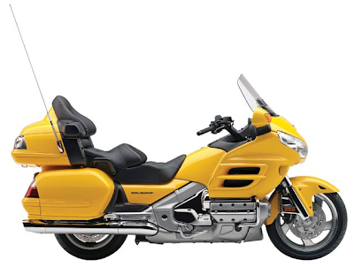
Honda GL1800 Specific Instruction Manuals

https://blogger.googleusercontent.com/img/b/R29vZ2xl/AVvXsEjC7oM3MzPEWk1qF9Z_kNLUVBdT1IX1Lx-mnlaPpS0o09A9eeG8LPA1hgcF8b9Ima9UzbUH_1J_DsojbcSx_h-8Tn5UVSgjpTsTGxuX2gdf1HNwCz6NS74FMZmK3jLCW1K7afffeUA3j9E/s400/HONDA+GOLDWING+1800cc+2009+glow.png


Short Description
This complete plug and play kit comes with two different power cables (only one will be used). You will decide if your lighted switches will be powered only when the bike ignition key is in the “on” or the “accessory” position or if they will be “always hot”. The “always hot” option is ideal for parking lights, parade style lights or anything you may want turned on when the key is either on or off. This is the recommended choice for use with an Owl Knight Rider, Windshield Lights or Owl’s Eyes on the GL1800. Use the appropriate installation instructions below.

Website: www.owllighting.com | Filesize: 1017kb
No of Page(s): 6

Content
Installation Instructions for “Always Hot” Switches
• Remove the following items per the Honda Service manual.
Seat
Left side battery cover
Left or Right side under handlebar cover
Left or Right side Pocket
• Carefully run the red/black power cable from the battery into the pocket on the same side your switches will be mounted. Start from the battery with the plastic connectors and route the wire along the upper frame member and under the edge of the top shelter, leaving the end with the battery ring terminals and fuse near the battery. Fish the wire into the faring pocket opening. Allowing enough wire to reach the battery terminals, pull all of the extra wire into the pocket area.
• Remove the ground wire from the battery and attach the ground (Non-fused) wire from the power cable, replace the battery ground bolt and secure it.
• Remove the positive wire from the battery and attach the positive wire (with the fuse holder) to the positive terminal of the battery, replace the battery bolt and secure it, replace the rubber boot over the positive battery terminal.


Get the file Download here

Honda GX22 GX31 Repair MANUAL

https://blogger.googleusercontent.com/img/b/R29vZ2xl/AVvXsEg4YqMwOlfLVTuDd1jwNhg9ZHQbZOw3vUH807pE9V5OSfMcf4COtL2rDYukdH8Uj2YWOkIPcB6Ef8sIPVUSikSoKzKdGYpDtxRlKfmXmLAojvIuJPC29IVh2cEdzE_jf-xSYlkgdvg6Hg8O/s400/2008+Honda+Accord+engine.jpg


Short Description
Thank you for purchasing a Honda engine. This manual covers the operation and maintenance of your engine: GX22 - GX31 All information in this publication is based on the latest product information available at the time of printing. Honda Motor Co. Ltd. reserves the right to make changes at any time without notice and without incurring any obligation. No part of this publication may be reproduced without written permission. This manual should be considered a permanent part of the engine and should remain with it if it is resold.

Website: www.waterrauk.com | Filesize: 667kb
No of Page(s): 16

Content

1. Engine oil level
CAUTION:
- Running the engine with insufficient oil can cause serious engine damage.
- Be sure to check the engine on a level surface with the engine stopped.
1. Place the engine horizontally on a level surface.
2. Remove the oil filler cap and check the oil level: it should reach the top of the oil filler neck.
3. If the level is low, fill to the top of the oil filler neck with the recommended oil.
Every 10 hours, check the engine oil level and replenish oil up to the top of the oil filler neck if the engine is operated for more than 10 hours continuously.

Use Honda 4-stroke, or an equivalent high detergent, premium quality motor oil certified to meet or exceed U.S. automobile manufacturer’s requirements for service classification SG, SF. Motor oils classified SG, SF will show this designation on the container. SAE 1OW-30 is recommended for general, all temperature use.


Get the file Download here

Honda Manual Transmission

https://blogger.googleusercontent.com/img/b/R29vZ2xl/AVvXsEjP7t6fGRRlNwfsIM-w1lNsbEf0xORV9Ha53_wJbulVA8kLVluBBiuXp8C6UKn5CHqCrPrJJAubjl5KUeyqUgELeCeLgzcicLgGlUvr0fygGcyMKrXRSWtItsKbBWExKNhUQNwD_5no1kVD/s400/2007+Honda+Civic+Type+S+1.8+i-VTEC+3d+interior.jpg


Short Description
The shift lever feels hard to move from gear to gear, or the manual transmission pops out of 2nd or 5th gear, usually during deceleration. The shift cable end is corroded at the transmission, which causes a stiff feeling when shifting (this may also cause the transmission to pop out of gear). The clearance between the interlock and transmission case wall is too large, and 2nd or 5th gear tooth contact length is too short, causing the transmission to pop out of gear.

Website: honda.justanswer.com | Filesize: 208kb
No of Page(s): 4

Content

Replace the cable bushings if corroded, or replace the transmission case housing, 1-2 shift fork, 2nd gear set, 1st gear, and 5th gear.

DIAGNOSIS
Test-drive the vehicle. Shift through all five gears and then back down to 2nd, and check if it is difficult to shift into gear. Accelerate at wide open throttle in 2nd or 5th gear, and quickly release the gas pedal; do this several times.
• If the transmission only has a stiff feel when shifting, go to REPAIR PROCEDURE A.
• If the transmission only pops out of gear, go to REPAIR PROCEDURE B.
• If the transmission has a stiff feel when shifting and pops out of gear, do REPAIR PROCEDURE A first, and then do REPAIR PROCEDURE B if needed.


Get the file Download here

Honda TRX400EX Installation Instruction

https://blogger.googleusercontent.com/img/b/R29vZ2xl/AVvXsEhuGbPcFnyPQmX8EetLBTFJGoOmInAVVIxlBAlKsgcbhr7YSL-XLxPub9fpWUol3sa1-12jyq2-zIh48lZSO35avMfPqWH9_FyvzD5Et58lejT5Ys-K4UfA6ahtvs3zxcmKqDFE2VW5mrE/s400/Mugen_Honda_Odyssey_002.jpg


Short Description
Spark Output: The Enhancer Ignition System for the Honda 400EX produces a high output spark that is approximately double the stock spark output. This increased spark energy allows the use of richer fuel mixtures or even exotic fuel such as alcohol. The MSD Ignition will put out approximately 30,000 volts to the spark plug.

Website: www.msdpowersports.com | Filesize: 629kb
No of Page(s): 8

Content
Spark Plugs: With the MSD Enhancer, it is recommended to use as cold a spark plug as possible while still being able to start the engine easily. The spark plug gap will largely depend on the compression of the engine. The higher the compression the smaller the plug gap you must run. A good rule of thumb for the spark plug gap is between .032” and .036”. Taking the time to test with different gaps will give you the best gap for your application.
MSD Coil and Spark Plug Wires: The MSD Coil features low resistance (0.2 Ohms Primary, 2K Ohms Secondary) with a turns ratio of 70:1 for maximum spark voltage and energy. The 8.5mm Super Conductor Spark Plug Wires are very low resistance (less than 50 Ohms per foot) for maximum voltage carrying capabilites. Even with this low resistance, the wire still suppresses EMI (Electro Magnetic Interference) from disrupting the electronics of the ignition. This is the only wire recommended to be used with the MSD Enhancer Ignition System.


Get the file Download here


2000 GLF1800 Oxygen Sensor Replacement

Short Description
The purpose of this Service Bulletin is to provide information to assist you in the replacement of both oxygen (O2) sensors on affected 2001 GL1800/A models. Moisture in the exhaust can damage the O2 sensors. Also, the right O2 sensor coupler can become corroded which will result in a non-functioning sensor. A replacement kit that contains two new O2 sensors is needed to repair the problem. Only perform this procedure if the vehicle actually experiences an O2 sensor failure.

Website: www.ridersrally.com | Filesize: 136kb
No of Page(s): 2

Content
REPAIR PROCEDURE
1. Remove the top shelter (see page 2-10 in the Service Manual).
2. Remove the left and right O2 sensors from the exhaust pipes.
• You do not have to remove the exhaust pipes to remove the O2 sensors.
• Be sure to note the wire routing for proper reassembly.
3. Install the new O2 sensors and route the wires properly (see pages 1-33 and 1-34 in the 2001-Service Manual).
4. Connect the black 4P female coupler of the subharness kit to the wire harness side black 4P male coupler (for the left-side O2 sensor).
5. Connect the new left O2 sensor to the black 4P coupler on the sub-harness.


Get the file Download here

Civic Rear Main Oil Seal Leaks

http://3.bp.blogspot.com/_FoXyvaPSnVk/TGQz71XRkiI/AAAAAAADMSw/61JI12R7C0Q/s1600/Honda-Civic-Lexus-Crown-3.jpg

Civic Rear Main Oil Seal Leaks
Short Description
SYMPTOM
The engine leaks oil between the block and the transmission.
PROBABLE CAUSE
The rear main oil seal (crankshaft oil seal) is contaminated.

Website: www.honda-fanatics.nl | Filesize: 71kb
No of Page(s): 2

Content
DIAGNOSIS
Clean the area with a shop towel where the engine block and transmission meet. Start the engine, and look for oil leakage from the area with the aid of a powdered leak detector.
• If you see any signs of leakage, go to REPAIR PROCEDURE.
• If you see no signs of leakage, then what looked like leakage may have been excess residue from a previous repair on another part. Continue with normal troubleshooting.
REPAIR PROCEDURE
1. Remove the transmission. Refer to section 13 or 14 of the appropriate service manual.
2. Remove and discard the rear main oil seal (crankshaft oil seal).
3. Install the new oil seal. Refer to page 7-29 of the ‘96–00 service manual or page 7-27 of the ‘01 service manual.
4. Reinstall the transmission.
5. Reinstall the drain plug with a new sealing washer.
6. Refill the transmission with the appropriate fluid.


Get the file Download here

Honda GXV50

https://blogger.googleusercontent.com/img/b/R29vZ2xl/AVvXsEiZSuLFHzsDx_G2xCrk9k37ZaR9TBW3L4SBKnlcAsxXykz3z4S_pGAjiNQVYjUT9YDVcidxl7YU9pCl1TvHAa9A8rsynQ4bJBiXqJ2pAJyrRfJP19IKOrMjVwrxFXzCv2PRJ3EdgAD98yE/s400/htup_0808_06_z%252B1996_honda_civic_coupe_ej%252Bb16b_engine.jpg

Short Description
Proper service and repair procedures are vital to safe, reliable operation of Go-Karts and Bumper Boats as well as personal safety of those performing repairs. Refer to your J&J Service Manual for servicing and repairing J&J Go-Karts and Bumper Boats. Always use safe and effective methods. The Service Manual contains many NOTES, CAUTIONS and WARNINGS which should be followed along with standard safety procedures to eliminate the possibility of personal injury or improper service which could be damaging to your equipment or compromise its safety.

Website: www.funpartsxpress.com | Filesize: 3150kb
No of Page(s): 25

Content
It is important to note that repair procedures, techniques, tools and parts for servicing Go-Karts and Bumper Boats as well as the skill and experience of the individual performing work vary widely. It is not possible to anticipate all conceivable ways or conditions under which Go-Karts and Bumper Boats may be serviced or to provide cautions to all possible hazards that may result. Standard precautions should be used when handling toxic or flammable fluids, and safety goggles or other protection should be used during cutting, grinding, chiseling, prying or any other process that can cause material removal or projectiles. J&J recommends use of safety goggles or approved glasses during all servicing.
All information contained in this Parts Guide is based on the latest product information and prices available at time of printing. We reserve the right to make changes at any time without notice. No part of this publication may be reproduced, stored in a retrieval system or transmitted, in any form by any means, electronic, mechanical, photocopying, recording, or otherwise, without the prior written permission of J&J Amusements, Inc. A Corporation of Oregon. This includes text, figures and tables.


Get the file Download here

Honda GL1800 Trailer Hitch Installation Instructions

https://blogger.googleusercontent.com/img/b/R29vZ2xl/AVvXsEi2F5L-o9hY-ucjIhbkaH2sontYgfKWj_lQ4mVUGGjEA1HCFzvp3zeS8EJ9XnVXaX3ZZ_FZGhscsM8BlkF88NB96sXju4pVWQWpDTSKTVocHuqisFz54k_SOZTzbpYgZAMkegjXqPvkmNU/s400/HONDA+GOLDWING+1800cc+2009.png

Honda GL1800

Short Description
THE BUSHTEC GL1800 VERTICAL RECEIVER HITCH SYSTEM HAS BEEN EXCLUSIVELY DESIGNED FOR USE ONLY ON A STOCK HONDA GL1800. IT WILL NOT WORK ON ANY OTHER MOTORCYCLE. ANY MODIFICATION TO ANY PART OF THIS HITCH, INCLUDING BUT NOT LIMITED TO ALTERING THE SUPPLIED HARDWARE OR IMPROPER INSTALLATION COULD CAUSE INJURY OR DEATH AND IMMEDIATELY VOIDS ANY AND ALL WARRANTIES.

Website: www.bushtec.com
Filesize: 70kb
No of Page(s): 9

Content

1. Place the motorcycle on its centerstand on level ground. Remove the four bolts in the seat handles with a 6mm Allen head socket and remove the seat. NOTE: The rubber bushings inside the seat may fall out during removal; Make sure they are in place upon reassembly.
2. Remove both side covers.
3. Remove the (5) five bolts in the rear fender (license plate panel, between saddlebags) with a 5mm Allen head socket. Remove the rear fender. NOTE: The fifth bolt is behind the license plate.
4. Remove the (3) three bolts in the passenger floorboard holder cover with a 5mm Allen head socket. Remove the cover and repeat for other side.
5. Remove the (2) bolts in the rear saddlebag guard with a 12mm socket. Remove the saddlebag guard and repeat for other side.
6. Remove the bolt in the muffler hanger using a 12mm socket. Repeat for other side.
7. Loosen, but do not remove, the muffler clamps using a 6mm Allen head socket. Rotate the mufflers down slightly to allow the hitch hoop to slide between the mufflers and the saddlebags.


Get the file Download here

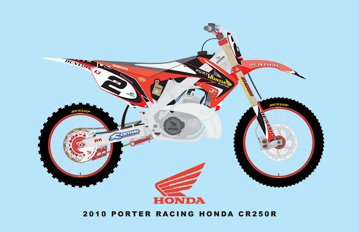
Honda CR 125/250R Installation Instruction manuals

https://blogger.googleusercontent.com/img/b/R29vZ2xl/AVvXsEjV15ZfGcgOWxvpuddBkovvIqB-GCTMaL9mZ98LeQggQzWrCnAq42tP0F5ZefkktqiKG5VlYAVbgkDCG2uQshOD8J2OegDt2SUCpBUmHnPebi2H8eKKHIOvDrtnIY0Wfc0nevkeUaO-894A/s730/2010+Porter+Honda+CR250R---1-13-10-printable.jpg

Honda CR 250R

Short Description
Note: The MSD Enhancer Ignition, PN KT4201, for the Honda CR 125 or CR 250R motorcycle is designed as a complete system. No part may be substituted with the stock ignition system.

Website: users.atw.hu
Filesize: 179kb
No of Page(s): 4

Content

The following explains some technical aspects of the Enhancer Ignition.
Battery: The battery is necessary to the operation of the Enhancer in two regards.
• The battery supplies voltage to the complex timing feature of the Enhancer.
• The Enhancer has a built in boost circuit that amplifies the spark energy at low rpm where the stock magneto is insufficient.
The MSD NiCad Battery pack, PN 4381, must be charged with the recommended battery charger or an MSD Fast Charger, PN 4385. The battery should be completely discharged before recharging. If a 7.2 Battery Charger is used, the recommended time for charging is seven hours. With the MSD Fast Charger the battery only needs to charge for one hour.


Get the file Download here

Honda Service Bulletin Safety Recall Ignition Switch

https://blogger.googleusercontent.com/img/b/R29vZ2xl/AVvXsEgkosn8L5ZLsbMDjB9hEo11ckMYiN0MR0Sfcq1-WMiH1xHVaAzI41uS-UGzT1b4_xsxfIgnMCsmGrNQb3iIRNiIi62BmmRSNkOUPrvorDXHiewehtTy1ZRFN2Zg8fKTAQUILr0YMEnrhx_I/s1600/2011-Honda-Odyssey-18.JPG

Honda Service Bulletin Safety Recall Ignition Switch

Short Description
Electrical contacts in the ignition switch can wear prematurely due to high electrical current passing through the switch. Worn out ignition contacts could cause the engine to stall without warning. Although the engine will restart in most cases, a vehicle that stalls while driving increases the risk of a crash.

Website: www.alancoxautomotive.com

Filesize: 586kb
No of Page(s): 7

Content

Not every vehicle in the years and models listed above is affected by this campaign. Before beginning work, verify that the vehicle is eligible by checking at least one of the following.
• The customer has a notification letter.
• The vehicle is shown on your campaign responsibility report.
• The vehicle is shown as eligible on a DCS or iN (Interactive Network) VIN Status Inquiry.

Procedure A: 1997 Accords (L4)
1. Remove the dashboard lower cover, the knee bolster, and the steering column covers (see the 1997 Accord Service Manual, page 23-75, steps 2 and 3).
2. Disconnect the 7P and 8P connectors from the ignition switch body.


Get the file Download here

Honda ENGINE BLOCK HEATER INSTALLATION INSTRUCTIONS

http://1.bp.blogspot.com/_FoXyvaPSnVk/THlLtomb96I/AAAAAAADPi4/pQq2JUPl1yA/s1600/Honda-CR-Z-Super-GT-04.jpg


Short Description
- Always use Honda Antifreeze/Coolant. Using a non-Honda coolant can result in corrosion, causing the cooling system to malfunction or fail.
- To avoid burning out the element, do not operate the engine block heater before it is installed in the vehicle or before you add coolant.

Website: www.cheaphondaparts.com | Filesize: 602kb
No of Page(s): 4

Content

1. Allow the engine and all cooling system components to cool down.
2. Make sure you have the anti-theft code for the radio, then write down the frequencies for the preset buttons.
3. Disconnect the negative cable from the battery.
4. Place a clean drain pan under the radiator drain plug, then remove the drain plug from the rear of the radiator to drain the coolant. Remove the radiator cap, and loosen the bleed bolt to increase the flow.
5. Remove the bolt with the washer from the engine block on the left side near the oil filter. Coolant remaining in the engine jackets will flow out of the bolt hole when the bolt is removed.


Get the file Download here

Honda Service Manuals-2002 Civic 3-Door and CR-V MIL

http://img216.imageshack.us/img216/1970/hondacivictyper20071it.jpg


Short Description
SYMPTOM
The MIL is on, and DTC P0341 [variable valve timing control (VTC) phase gap] is set.
PROBABLE CAUSE
The VTC control solenoid valve is temporarily stuck or contaminated.

Website: www.crvownersclub.com | Filesize: 82kb
No of Page(s): 1

Content

REPAIR PROCEDURE
1. Use the PGM Tester to read and clear the DTC(s).
2. Start the engine, and let it idle.
3. Check the engine idle:
• If the engine does not idle smoothly, go to step 4.
• If the engine idles smoothly, go to step 5.
4. Replace the VTC control solenoid valve. Refer to page 11-127 of the 2002 Civic Si Service Manual or page 11-133 of the 2002 CR-V Service Manual.
5. Make sure you have the Interactive Network (iN) CD (July ‘02 or later) loaded into your iN master terminal. If not, load the CD using the instructions that come with it.
6. Update the ECM/PCM software with the Honda Interface Module (HIM). Refer to S/B 01-023, Using the Honda Interface Module to Update Control Units/Modules.


Get the file Download here

Hummer H3 Automatic Transmission

[Carscoop_H3Alpha_6.jpg]


Short Description
Remove the turbocharger system from its carton and inspect for any obvious physical damage. All kit components are thoroughly inspected and carefully packaged prior to shipment from the factory. If any shipping damage is evident, contact your supplier and request that they process a claim with the shipper involved. Be sure to review the parts list on page 3 to verify that you have all necessary system components to proceed. If any components in the parts list are missing, contact Turbonetics’ customer service staff.

Website: www.turboneticsinc.com | Filesize: 5695kb
No of Page(s): 62

Content

Prerequisite Step: ECU Removal & Shipping
Before getting your hands dirty while under the hood, there is one prerequisite step. Prior to turbo kit installation the ECU (Engine Control Unit) needs to be removed from the car and shipped to Turbonetics in order to load the new engine management program. This program is tuned specifically for your car with this turbo setup.
NOTE 1: You’ll want to perform this step just before you are ready to start working on the car. When you receive your ECU back from Turbonetics, it will be re-programmed for a turbocharged engine and therefore will no longer work properly with your naturally aspirated “stock” engine. The included ECU return box kit (P/N 11103) includes a pre-paid Fedex shipping label for express shipping, so you can expect to receive your ECU back in 2-3 days.
NOTE 2: If, in the future, you choose to remove the turbocharger system (for example, before selling the car), it is possible to re-program your ECU back to naturally aspirated “stock” specs. At that time, contact Turbonetics’ customer service staff for details.


Get the file Download here

HUMMER H3 Authentic HUMMER Style and Capability in a Midsize Package

[Hummer3T_2.jpg]

HUMMER H3 Authentic

Short Description
• Trademark HUMMER style and off-road capability
• Vortec 3.5L inline five-cylinder with 162 kW (220 horsepower) at 5600 rpm and (305 Nm) of torque at 2800 rpm
• Choice of manual or automatic transmission
• Electronically controlled four-wheel-drive system
• Uncompromised off-road capabilities along with refinement, comfort and convenience
• Bold, iconic HUMMER exterior design
• Inviting, modern interior, blending premium cues with world-class craftsmanship

Website: www.gmeurope.info | Filesize: 58kb
No of Page(s): 5

Content

“The H3 is an extraordinary new presence in the world of midsize SUVs,” said Martin Walsh, HUMMER general manager. “HUMMER has developed a passionate following because of its unmatched style and capability, and the H3 extends that appeal by making the brand accessible to a broader range of potential owners.”
H3 packs uncompromising HUMMER style and capability into its midsize dimensions. Compared to the H2, the H3 is 429 mm shorter in length, 152 mm shorter in height and 165 mm narrower. Roughly the same length as a family sedan, H3 can navigate city traffic and also deliver HUMMER’s trademark crawling and climbing capability.
Powered by the Vortec 3.5L engine with dual overhead cams and variable valve timing, the H3 reaches a peak fuel economy of up to 11.8 l/100km. Specifically designed for this type of vehicle, the Vortec 3.5L inline five-cylinder offers an excellent combination of power and efficiency. It delivers 162 kW (220 horsepower) at 5600 rpm and 305 Nm of torque at 2800 rpm.


Get the file Download here

Krystal Hummer Owners Manual PDF

[Hum_CAR_91.jpg]

Krystal Hummer Owners Manual

Short Description
You have taken ownership of a true luxury vehicle which is in a class all its own. We are providing this manual to familiarize you with your new Krystal HUMMER SUV. This manual shall serve as a reference document for the operation and maintenance procedures that shall be required throughout the life of your vehicle. This edition covers all our HUMMER models, and is designed to be used in conjunction with the original chassis manufacturer’s owner’s literature, as well as all other component manufacturer’s literature.

Website: www.policevehicle.com | Filesize: 288kb
No of Page(s): 10

Content

Safety Belts and Occupants
All Krystal HUMMER models are equipped with a quantity of seat belt assemblies equal to the maximum number of occupants that can legally be seated in each passenger compartment. The allowable number of occupants is dependent upon the length of your vehicle and several other factors. That information can be found on the chart shown on page 43.

VEHICLE STOPPING DISTANCE
Even though limousines are equipped with heavy-duty, anti-lock braking systems, SUV limousines do require more distance to stop. We encourage you to take time to understand and experience the difference in time/distance that is required to bring your new vehicle to a safe stop. This time/distance factor is also effected by the number of passengers you are carrying.


Get the file Download here

HUMMER H3 2006 Service Manuals

[Hummer_H3-Concepts-SEMA_4.jpg]

HUMMER H3 2006 Service Manuals

Short Description
The smallest Hummer shares its platform and mechanical components with the Chevrolet Colorado and GMC Canyon. It’s powered by a 3.5 litre five-cylinder engine. In terms of size, the Hummer is most comparable to the Jeep Grand Cherokee and Nissan Pathfinder.

Website: www.caaquebec.com | Filesize: 92kb
No of Page(s): 5

Content
Interior and trunk
Because of its height and optional running boards that are dirt magnets and more cumbersome than they are useful; getting into the vehicle can be a difficult, dirty endeavour. The front seats are very comfortable thanks to the adjustable-tilt seat cushion. The driving position is good, but there isn’t a lot of footroom for the driver or the front passenger.
Getting into the back is even harder than the front because the doors don’t open very wide and expose part of the often dirty rear tires, which are easy to brush againts. The rear seat is comfortable for two adults. Headroom and legroom are good. The rear seatback splits 60/40.
Trunk capacity is not very impressive, and worse than all the competition. Even with the rear seat folded, cargo space is lacking. The door opens wide and in the right direction, i.e., to the left. There is space for a container for wiper fluid on each side of the trunk.


Get the file Download here

Roof Rack Assembly/Mounting Instructions

https://blogger.googleusercontent.com/img/b/R29vZ2xl/AVvXsEjU6ybxdvzQTMaEs-i7MZEtwKL5kdMeFw_GXsZzV-Y2tUdsw3gNVUrBTwmuctEkXYymx14CrxL-T6hI8BSqSpfr9YEAryYnfX0diecrtmOLx50MVaMxbklgNqn-KkpMJjVl7SeE6F167iY/s1600/Hummer-H2-Ultimate-Six-9.jpg

Roof Rack Assembly/Mounting Instructions

Short Description
1) Before beginning assembly/installation, please check to make sure you have received all of the contents as listed above.
2) Lay the roof rack halves upside down on a level, non-marking/non-scratching surface and align. Join the two halves together using the provided 5/16” X 18 X 1_ ” stainless hex bolts and Nylock nuts (8 each). Tighten securely. Before installing the Nylock nuts, lubricate the bolt threads with grease or a similar anti-seize lubricant.

Website: www.addavent.com | Filesize: 716kb
No of Page(s): 1

Content

3) With the rack still upside down, install the 3/8” X 16 X _” stainless hex bolt /stainless washers (24 each) up through the rack and into Oval Bar T-Nuts (24). Tighten bolt one turn only. Slide the Oval Bars onto the T-Nuts, centering Oval Bars under rack. Snug all bolts.
4) Adjust the position of the eight (8) factory attached Rack Brackets so that they are positioned approximately 5/8” from each end of the Oval Bars. Remove existing Hummer H2 top bars (refer to Hummer H2 Owners Manual for removal instructions).
5) Remove existing Hummer H2 top bars (refer to Hummer Owners Manual for removal instructions).
6) Place the assembled roof rack on vehicle located on the existing roof channels.
7) Place a Rack Bracket T-Nut (16) into the slot of the existing roof channel adjacent to each end of the Rack Brackets. The chamfered side of the T-Nut must be facing down (see photo below). Slide these T-Nuts under the Rack Brackets until they are aligned with the Rack Bracket holes.


Get the file Download here

Kawasaki ER-5 Motorcycle Service Manual PDF

https://blogger.googleusercontent.com/img/b/R29vZ2xl/AVvXsEh31iHSZPzwJiiCyAyQfRDw16hOuuzzb9GqoUxTDvVWWuLPqyKe7aHObi4ucRBO7wwXXU0uW76t3LqhvhdLOSCGqGQvMfHNhp_3GgIb07KDjPw8Oqnb3AsOKZRmNZoYzpalK5YA41ecZmeK/s320/kawasakiEr5s-013-f.jpg


Short Description
This manual is designed primarily for use by trained mechanics in a properly equipped shop. However, it contains enough detail and basic information to make it useful to the owner who desires to perform his own basic maintenance and repair work. A basic knowledge of mechanics, the proper use of tools, and workshop procedures must be understood in order to carry out maintenance and repair satisfactorily. Whenever the owner has insufficient experience or doubts his ability to do the work, all adjustments, maintenance, and repair should be carried out only by qualified mechanics.

Website: users.atw.hu | Filesize: 7145kb
No of Page(s): 334

Content

Torque and Locking Agent
Tighten all bolts and nuts to the proper torque using an accurate torque wrench. An insufficiently tightened bolt or nut may become damaged or fall off, possibly resulting in damage to the motorcycle and injury to the rider. A bolt or nut which is overtightened may become damaged, strip an internal thread, or break and then fall out. The following table lists the tightening torque for the major bolts and nuts, and the parts requiring use of a non-permanent locking agent or liquid gasket. When checking the tightening torque of the bolts and nuts, first loosen the bolt or nut by half a turn and then tighten it to the specified torque.

Do not use compressed air on an assembled carburetor, or the floats may be crushed by the pressure, and the vacuum piston diaphragms may be damaged. Remove as many rubber or plastic parts from the carburetor as possible before cleaning the carburetor with a cleaning solution. This will prevent damage to or deterioration of the parts. The carburetor body has plastic parts that cannot be removed. Do not use a strong carburetor cleaning solution which could attack these parts; instead, use a mild, high flash-point cleaning solution safe for plastic parts. Do not use wire or any other hard instrument to clean carburetor parts, especially jets, as they may be damaged.


Get the file Download here

Bentley Hummer H3

[Carscoop_H3Alpha_5.jpg]

[Carscoop_H3Alpha_3.jpg]

Short Description
The objective of the following analysis is to determine the marketing strategy(s) applied to the (General Motors) Hummer H3 and whether or not this strategy(s) is consistent – and effective – throughout the product’s marketing mix. The strategy(s) will be evaluated, and recommendations made.

Website: www.chrisbentleyinfo.com | Filesize: 395kb
No of Page(s): 8

Content
The Hummer (High Mobility Multi-Purpose Wheeled Vehicle, or HMMWV) was originally developed for the U.S. Army circa 1980 by AM General. With only slight modifications this vehicle, now known as the H1, was made available to the general public in 1992 (’93 model). However, in 1999 AM General sold the Hummer name and distribution / selling rights to General Motors. The H2, also made by AM General in South Bend, Indiana, was introduced in July of 2002 (’03 model), and the most recent Hummer offering – the H3 – was introduced in the spring of 2005.
The Hummer brand means big (read: over-sized, as most H1’s and H2’s won’t fit in standard garages) and rugged, capable of going anywhere, anytime. The brand represents the ultimate man’s man SUV, because it was made for conquests. It was a vehicle designed for war that’s now available to civilians; owning a “war machine” is about as macho as it gets. And it comes priced at a premium. No surprise the brand attracts highly affluent males (incomes well above $100,000). The Hummer’s take-no-prisoners off-road capabilities are legendary, as is Hummer’s “iconic” styling. In this regard, the H3 is no different than the H1 and H2 models.


Get the file Download here

The Magazine for Hummer

[Carscoop_H3Alpha_4.jpg]

Hummer

Short Description
Gas prices have fallen a tad, and with that SUV sales have risen. See how they control us like puppets? And now with falling fuel prices they want to cut production to stop a gallon of gas from from getting any cheaper. But even when gas prices hovered over $3, Hummer sales, especially the H3 continued to rise. And with the newly opened South African plant, and with strong hints of a forthcoming H4, the HUMMER name continues its forward momentum.

Website: www.thehummerexperience.com | Filesize: 5429kb
No of Page(s): 68

Content
This issue we visit with X Concept Motorsports for the exclusive unveiling of its X Concept SRV. Casborn Design and X Concept Motorsports have spent over three years finalizing the designs, through costly R&D, to come up with the final product. The X Concept SRV represents a whole new world for custom vehicles that cater to each individual owners needs. They even have an off road model on its way.
Then we take a look at the Berzerker, as Angry Iron shows us that deep pockets are not always necessary. After that, we fly back to Vegas to visit the over the top All4Show Hummer, which is perfectly suited for the city of overindulgence.
And if you’re looking to add larger rubber to your Hummer, or if you’ve already done so, then you undoubtedly have some form of rubbing. Especially up front. With full lift kits pricey, and sometimes not sensible, you usually are left having to deal with it. Well an unfortunate air compressor failure (Thanks for the repair SUN Hummer) caused by my rubbing tires up front has left me seeking options, especially for someone living in a city that doesn’t have enough tall parking garages to accommodate a full suspension lift. This issue in Product Profile we take a look at the popular method of turning up your torsion keys to squeeze out some extra inches.


Get the file Download here

Instructions for Installing the Scootworks Preload Improvement Kit on Kawasaki 400/800

https://blogger.googleusercontent.com/img/b/R29vZ2xl/AVvXsEj-2JUUJLGL-xxKmfUiWwydO7vyTPXgfD4dveRd-7cw5jjIffuyEVeC5SfCT1i0RnFCD82bSemERAcxwBAq1aI8eXSbJBNa4436KesmF3srsWi6XiiPobiRrluNtE3G7d8WBZgR95PkKF3g/s1600/kawasaki-ninja-zx-rr-800cc-wallpapers.jpg


Short Description
This instruction booklet contains detailed steps for installing the rear suspension preload improvement kit on your Kawasaki 400/800 Standard (A model), Classic, or Drifter motorcycle. Please pay careful attention to the instructions regarding the disassembly and re-assembly of your motorcycle. If you have any questions concerning installation of your new Scootworks Preload Improvement Kit, please contact us via e-mail at support@scootworks.com. This will ensure you receive the most prompt and accurate reply.

Website: www.scootworks.com | Filesize: 129kb
No of Page(s): 11

Content

The shipping container and contents must be inspected by the purchaser for damage to goods immediately upon receipt of goods, and a claim must be filed with the carrier if damage is discovered. The purchaser must contact Scootworks within 24 hours from receipt of damaged goods to file a claim, and for further instructions.

1. Begin by removing both side compartment covers. The RH compartment cover requires the use of the ignition key for removal; the LH compartment cover is secured by a large Phillips screw. Once you’ve removed the LH cover, place the Phillips screw back into the hole in the frame (so you don’t misplace it) and set both covers aside. In many applications, you must remove the upper exhaust pipe (from the rear cylinder), and loosen the other pipe, to remove the inner parts of the RH side compartment cover (see below). Before attempting step #2 below, try step #3 first… depending on the brand of exhaust pipes you have, you may be able to avoid removal in step #2, if you are successful with step #3 first. Some brands of exhaust pipes provide access to the fasteners securing the RH side covers, eliminating the requirement to remove pipes for rear suspension access.
2. Remove the rear cylinder’s exhaust pipe. To do so, remove the two Allen nuts on the exhaust header, where it attaches to the engine, using an 8mm Allen wrench. Most often, this goes much more smoothly if you first spray the inside of the allen nut with a penetrating lubricant like WD-40. Remove the black acorn nut from the discharge end of the exhaust pipe (under the upper exhaust pipe, near the discharge end of the pipe) using a 12mm open-end wrench or socket. You’ll find a black metal spacer, through which the bolt goes, that is pressed through the rubber grommet. To avoid the potential of having it fall out unnoticed, remove it and place it aside with the nut. Remove the black bolt from the pipe just aft (to the rear) of where the pipe enlarges and above the pipe. This is actually a bracket that holds the two pipes together at a joint. Loosen the bolt using a 12mm socket, then slide it back onto the pipe you’re removing. Once you have the pipe off of the bike, the clamp will be loose. Be sure to keep it with the pipe, along with the rest of the removed parts. Loosen the pipe from the front cylinder BEFORE trying to remove the pipe from the rear cylinder. By loosening the header nuts on the pipe from the front cylinder, and removing the two black Allen bolts (6mm Allen wrench) under the forward pipe that attach it to the frame, you will be able to remove the rear pipe. There are more spacers in grommets where the 6mm Allen bolts secure the lower pipe to the frame (like those used in the rearmost connection of the rear cylinder’s pipe). These spacers will normally remain in the frame bracket, but if either is loose, remove them and store with the Allen bolts. If the pipe doesn’t come loose relatively easily, loosen the two top nuts on the black triangular metal bracket used to secure the pipes to the frame. With patience and care, however, you should be able to remove the pipe without loosening with the triangular bracket.


Get the file Download here

Kawasaki Vulcan VN800 Valve Adjustment Maintenance Procedure Instructions

https://blogger.googleusercontent.com/img/b/R29vZ2xl/AVvXsEhWfsmIh74UdntytchNujiQqfGb6stm6eSWFFllzGbT83FkmTma1Ly6pJGvFVVL9c44RPOKVhf4yfmckC3WGAyLM_EX7d0atFp_s4P3bFemXHmM5-V9ZNXFGdT7Ew-KYpPn7EkPDV9VGao/s320/Kawasaki_VN-800_Vulcan_Classic_2C_2004.jpg


Short Description
Tools Required: Torque wrench, 8, 10, 12 and 17mm 6 point sockets. Big Ass Phillips screwdriver. Set of METRIC feeler gauges. Digital METRIC caliper. You can pick up a caliper from Harbor Freight cheap and the feeler gauges from Snap-On for less then $5.00. Using them eliminates the potential for errors in conversions.

Website: www.kawasakimotorcycle.org | Filesize: 1058kb
No of Page(s): 14

Content
The subject in the accompanying pictures in a non-California version 2001 Vulcan VN800A with the “Cool Off” EPA removal mod performed. As we cannot address all the possible modifications that can be done, these instructions are written as if the bike is in stock form and you will have to make any adjustments necessary to accommodate mods to your specific bike. This is a very easy procedure that should not take more then four hours to perform with the actual valve adjustment only taking a few minutes but like most things, preparation is the key to success. As the engine internals will be open to the environment for a time, it is recommended this be done in doors. As the engine coolant must be drained, this is a very good time to flush the system and replace it as well.
Disassembly: There are shortcuts than can be taken but experience has shown me this is the best procedure to follow as Murphy’s law ensures you will do it all 99 times out of 100 anyway. The engine must be cold, i.e. not run for a good eight hours before starting this procedure. Remove the seat and fuel tank. Things should now look like as they do in figures VA01 and VA02. Our objective is to get things looking like figures VA03 and VA04. As you remove bolts and screws, put them back in after removing the component so they will not be lost and you won’t have to go looking for them during assembly. Using a 10mm socket, remove the two bolts holding the upper airbox chamber, pull the chamber up to remove and set aside. Remove the air filter cover with a 10mm socket. Remove the air filter. Using the same 10mm socket, remove the two chrome bolts that hold the airbox backing plate on. The backing plate does not need to be removed, just pull it loose from the carb and drop it down and turn clockwise until it is below the level of the valve covers. Use a wire tie or safety wire to secure it. Disconnect the carburetor float bowl vent tube from the carb and pull it along with the speedometer cable and fuel tank vents tube(s) back and down until they are completely out of the way of the rear valve cover. Even behind it. Cut all wire ties as needed to get all the tubes out of the way but remember where they were for assembly. Disconnect the coolant overflow tube from the back of the thermostat housing and pull it back and down until it is completely out of the way of the rear cylinder valve cover, even behind it. Now move to the left side of the bike and disconnect the EPA gold valve tube (or bypass) from the valve covers. Just let it lay down between the jugs with the fuel line. Pull the spark plug wires and get them out of the way. Remove the two large screws shown in figure VA05 and swing the choke cable over so that it lays between the jugs with the other lines. Set a drain pan under the bike and remove the 10mm coolant drain bolt show in figure VA06. Open the coolant fill cap on the top of the thermostat housing to speed draining of the coolant. Using a 10mm socket, remove the two bolts holding the thermostat housing to the frame shown in figure VA07. Using an 8mm socket, remove the bolt holding the Y coolant hose connector from the frame as shown in figure VA08. Using a Phillips screwdriver, loosen the hose clamps from the two coolant hoses attached to the top of the engine and disconnect the hoses. Swing the assembly up and position it on top of the frame as shown in figure VA07. We are now ready to remove the valve covers but I recommend using a rag and spray cleaner to clean any and all dirt from the frame and components above the valve covers to prevent it falling into the engine while the covers are off. Using the 10mm socket or wrench, remove the three chrome bolts on the top of both valve covers. Starting at the rear of the front valve cover, work a small flat screw driver between the valve cover and the gasket to break it loose and work around the cover until it is no longer stuck to the gasket. Now lift the cover straight up until it clears and remove to the left side of the bike. Note that the spark plug sleeve, shown in figure VA09 may stick preventing horizontal movement of the cover. If this happens, push it back down into the cylinder head with your finger through the spark plug hole while lifting up on the valve cover.


Get the file Download here