Short Description
Tools Required: Torque wrench, 8, 10, 12 and 17mm 6 point sockets. Big Ass Phillips screwdriver. Set of METRIC feeler gauges. Digital METRIC caliper. You can pick up a caliper from Harbor Freight cheap and the feeler gauges from Snap-On for less then $5.00. Using them eliminates the potential for errors in conversions.
Website: www.kawasakimotorcycle.org | Filesize: 1058kb
No of Page(s): 14
Content
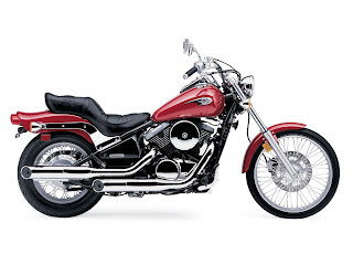
The subject in the accompanying pictures in a non-California version 2001 Vulcan VN800A with the “Cool Off” EPA removal mod performed. As we cannot address all the possible modifications that can be done, these instructions are written as if the bike is in stock form and you will have to make any adjustments necessary to accommodate mods to your specific bike. This is a very easy procedure that should not take more then four hours to perform with the actual valve adjustment only taking a few minutes but like most things, preparation is the key to success. As the engine internals will be open to the environment for a time, it is recommended this be done in doors. As the engine coolant must be drained, this is a very good time to flush the system and replace it as well.
Disassembly: There are shortcuts than can be taken but experience has shown me this is the best procedure to follow as Murphy’s law ensures you will do it all 99 times out of 100 anyway. The engine must be cold, i.e. not run for a good eight hours before starting this procedure. Remove the seat and fuel tank. Things should now look like as they do in figures VA01 and VA02. Our objective is to get things looking like figures VA03 and VA04. As you remove bolts and screws, put them back in after removing the component so they will not be lost and you won’t have to go looking for them during assembly. Using a 10mm socket, remove the two bolts holding the upper airbox chamber, pull the chamber up to remove and set aside. Remove the air filter cover with a 10mm socket. Remove the air filter. Using the same 10mm socket, remove the two chrome bolts that hold the airbox backing plate on. The backing plate does not need to be removed, just pull it loose from the carb and drop it down and turn clockwise until it is below the level of the valve covers. Use a wire tie or safety wire to secure it. Disconnect the carburetor float bowl vent tube from the carb and pull it along with the speedometer cable and fuel tank vents tube(s) back and down until they are completely out of the way of the rear valve cover. Even behind it. Cut all wire ties as needed to get all the tubes out of the way but remember where they were for assembly. Disconnect the coolant overflow tube from the back of the thermostat housing and pull it back and down until it is completely out of the way of the rear cylinder valve cover, even behind it. Now move to the left side of the bike and disconnect the EPA gold valve tube (or bypass) from the valve covers. Just let it lay down between the jugs with the fuel line. Pull the spark plug wires and get them out of the way. Remove the two large screws shown in figure VA05 and swing the choke cable over so that it lays between the jugs with the other lines. Set a drain pan under the bike and remove the 10mm coolant drain bolt show in figure VA06. Open the coolant fill cap on the top of the thermostat housing to speed draining of the coolant. Using a 10mm socket, remove the two bolts holding the thermostat housing to the frame shown in figure VA07. Using an 8mm socket, remove the bolt holding the Y coolant hose connector from the frame as shown in figure VA08. Using a Phillips screwdriver, loosen the hose clamps from the two coolant hoses attached to the top of the engine and disconnect the hoses. Swing the assembly up and position it on top of the frame as shown in figure VA07. We are now ready to remove the valve covers but I recommend using a rag and spray cleaner to clean any and all dirt from the frame and components above the valve covers to prevent it falling into the engine while the covers are off. Using the 10mm socket or wrench, remove the three chrome bolts on the top of both valve covers. Starting at the rear of the front valve cover, work a small flat screw driver between the valve cover and the gasket to break it loose and work around the cover until it is no longer stuck to the gasket. Now lift the cover straight up until it clears and remove to the left side of the bike. Note that the spark plug sleeve, shown in figure VA09 may stick preventing horizontal movement of the cover. If this happens, push it back down into the cylinder head with your finger through the spark plug hole while lifting up on the valve cover.
…
Get the file Download here